General Information and Specifications – 8
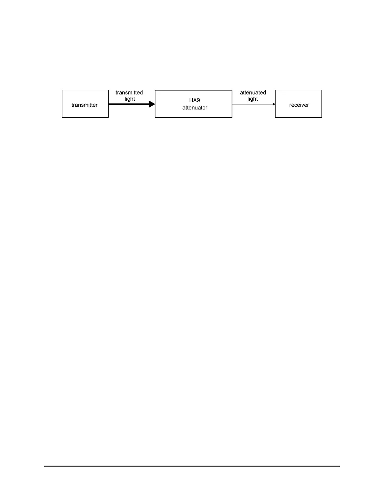
When combined with a light source, the attenuator can be used for EDFA testing or for
calibrating the linearity of power meters. In addition, the attenuator can be used for loss
simulation and for measuring bit error rate (BER) curves and the dynamic range of receivers
(Figure 2).
Figure 2: Block Diagram
Linearity
The linearity of the attenuation is not affected by wavelength.
Insertion Loss
Insertion loss is not included in the attenuation of the attenuator.
Source Considerations
Source output powers can be sensitive to reflections. For example, if the output of the
attenuator is connected to a jumper with an unterminated, non-angled connector (for example,
an FC/PC connector coupled into a detector), a large reflection can be coupled back into the
source when the attenuator is used at low attenuation settings. Consequently, as the
attenuation is increased, the reflection level back into the source decreases, making the HA9
attenuator seem non-linear over the range of 0 to 10 dB.
The following methods can be used to offset the effects of reflection:
• Using an angled connector (for example, an FC/APC connector) at the detector
• Adding some attenuation (5 to 10 dB typically) between the source and the attenuator
• Using an isolator between the source and the attenuator
Key Features
• 0.01 dB resolution and repeatability
• 0 to 100 dB attenuation range
• 1200 to 1700 nm or 750 to 1700 nm wavelength ranges
• Single-mode or multimode fiber
• Built-in beam blocking switch
• Less than 2.5 seconds from 0 to 100 dB
• IEEE 488.2 and RS232 interfaces
• SCPI compatible command set
• Universal connector adapter (UCA) option
• LabVIEW drivers
Artisan Technology Group - Quality Instrumentation ... Guaranteed | (888) 88-SOURCE | www.artisantg.com
 Loading...