Getting Started – 16
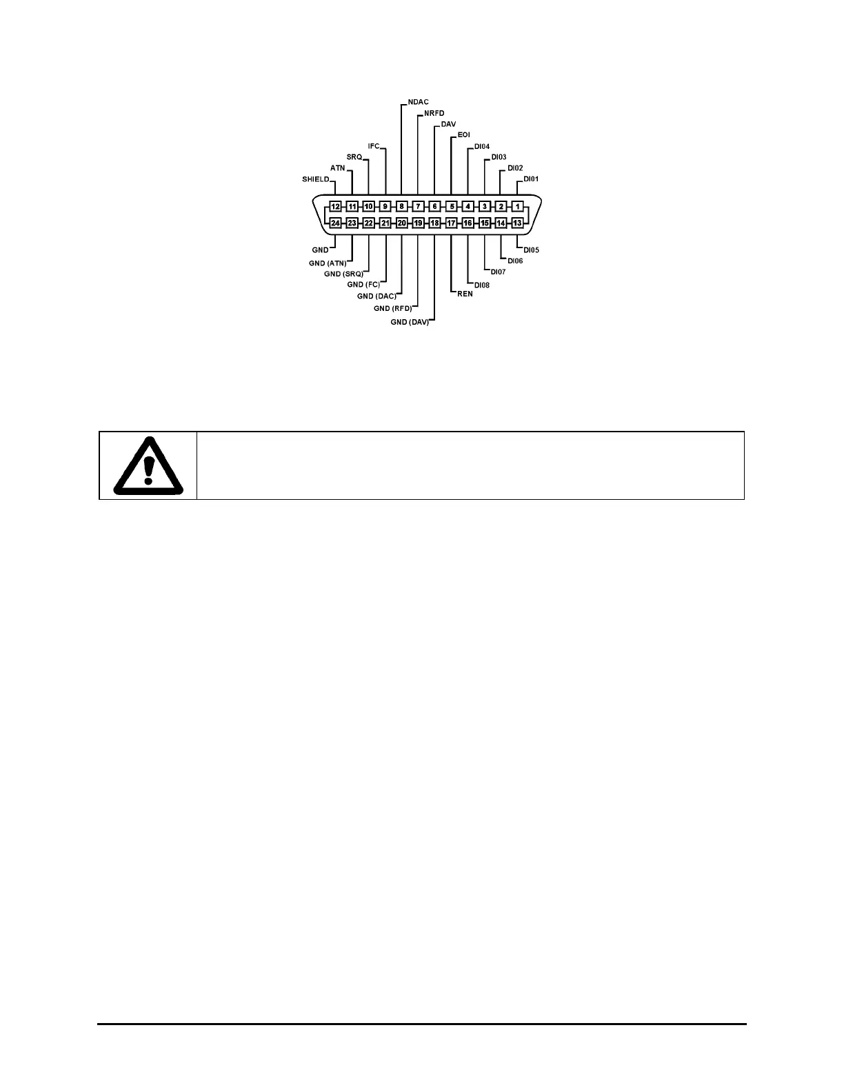
Figure 4: GPIB Pin Assignment
2. Connect the cable to the remote terminal and to the IEEE488 (GPIB) port at the back of the
attenuator.
Caution
Tighten the connector lock screws by hand. Do not use a screwdriver.
Next, set or reset the GPIB address and the command set:
1. Ensure that the attenuator is powered off (O).
2. Turn on the power switch (I) and, while the unit powers on, press and hold the LCL key.
The "GPIB setup" message is displayed. The previous mode, if any, is displayed, for
example, SCPI(LF) 5. The command set HA9, HPM, or SCPI message-terminating
sequence
<CR> <LF>, <CR> or <LF> (TR), and the GPIB address are displayed, for example, SCPI
(LF) 5. For the HA9 and HPM command sets, the message-terminating sequence is
permanently set to <CR> <LF>.
3. Press the related ▲ / ▼ key to change the command set and the GPIB address.
4. Press the ATT/PWR key. Until manually reset, these settings are used each time the
attenuator is powered up.
Connecting the RS232 Interface
The attenuator can be operated remotely using the RS232 interface. The nine-pin RS232
cable is user-supplied. When remote operation by the RS232 interface is required, make the
connection:
1. Check the RS232 cable to ensure that the pin assignment is correct (Figure 5). Use a
straight-through cable.
Artisan Technology Group - Quality Instrumentation ... Guaranteed | (888) 88-SOURCE | www.artisantg.com
 Loading...