Operating and Maintenance Instructions – 19
Key Description
MIN When held down for one second, sets the unit to the minimum
loss position
▲ / ▼
Increases (▲)/decreases (▼) the attenuation, power offset, and
wavelength calibration settings. Each pair controls a digit in the
corresponding position displayed on the LCD (except for
wavelength setting).
Status LEDs
The status LEDs are described in Table 5.
Table 5: Status LEDs
LED Description
OFFS Indicates that the unit is in Display Offset mode
REM Indicates that the unit is in Remote mode. All the front-panel keys except LCL are
locked out.
LOCK Indicates that the unit is in Local Lockout mode. The function of the LCL key is
disabled, and all front-panel keys are locked out.
ADDR Indicates that the GPIB interface is in Talk or Listen state
SRQ Indicates that the unit interrupt logic has generated a service request interrupt on
the GPIB interface
Connector Panel
Two fiberoptic connectors, or cable feed-throughs, are mounted on a removable panel. The
HA9 attenuator with a built-in splitter or switch has three fiberoptic connectors.
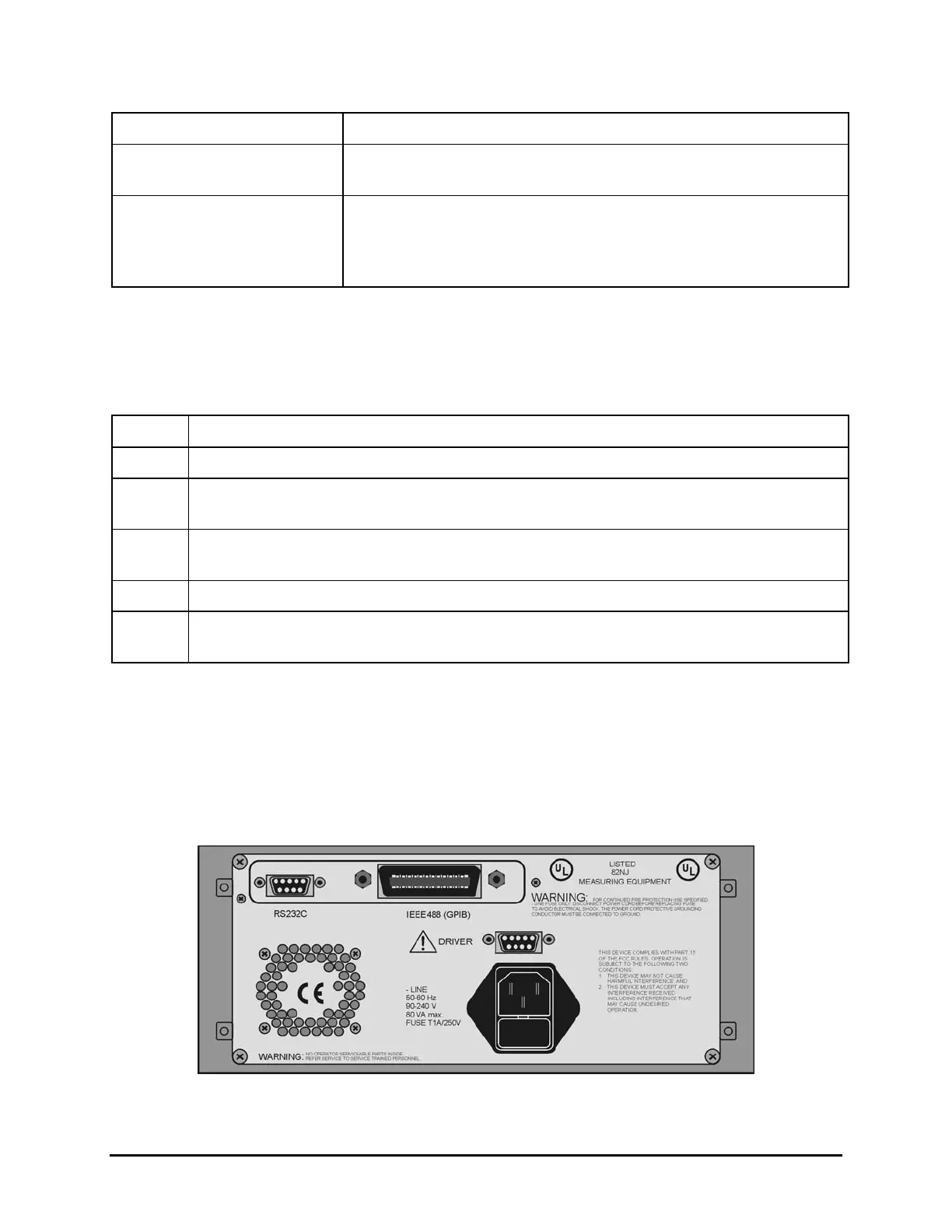
Rear Panel
The back of the attenuator is shown in Figure 8.
Figure 8: Back of the Attenuator
Artisan Technology Group - Quality Instrumentation ... Guaranteed | (888) 88-SOURCE | www.artisantg.com
 Loading...