Operating and Maintenance Instructions – 18
Operating and Maintenance Instructions
Front Panel
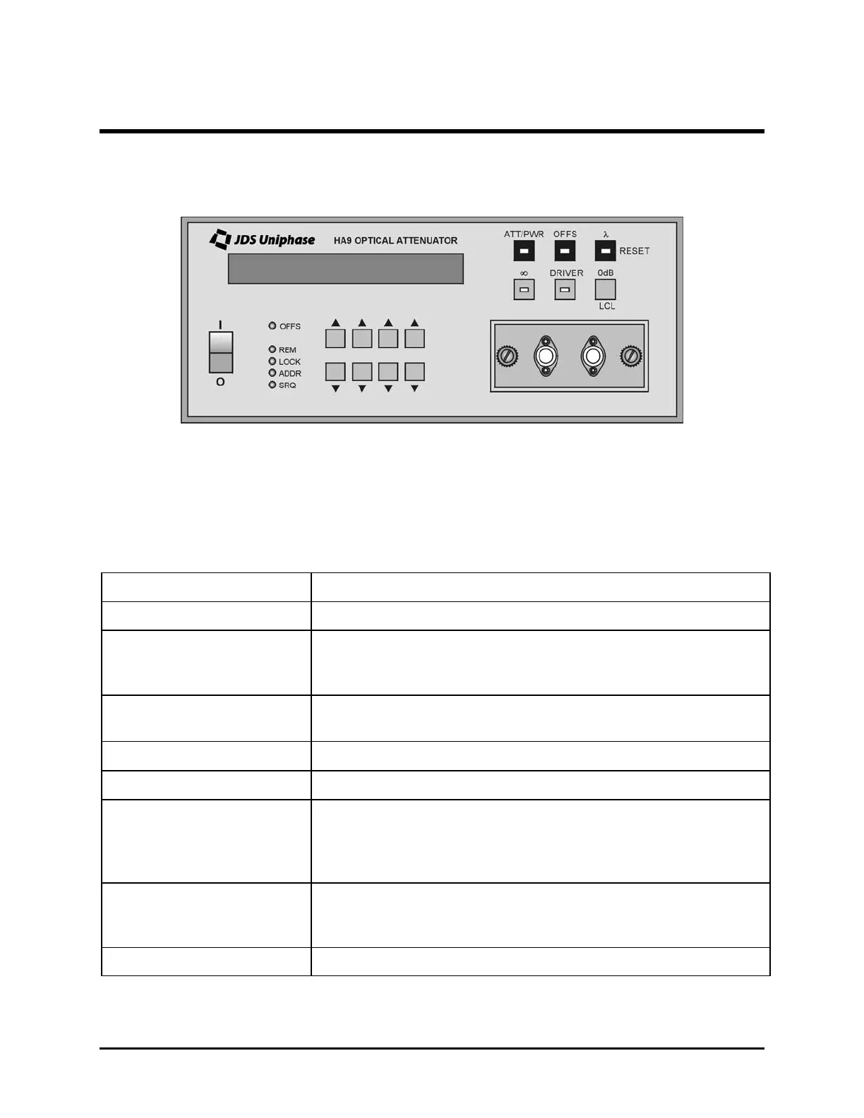
The front of the attenuator is shown in Figure 7.
Figure 7: Front of the Attenuator (varies with model)
Operating Keys
The operating keys are described in Table 4.
Table 4: Operating Keys
Key Description
I / O
Power on (I) /off (O) switch
ATT/PWR Sets the unit to Attenuation (ATT) mode to display attenuation
in dB or to Power (PWR) mode to display the optical power out
in dBm
OFFS Sets the unit to Display Offset mode. The ATT and PWR
displays can be offset separately.
λ
Sets the unit to Calibration Wavelength mode
∞
Controls the on/off status of the beam block
DRIVER (reserved for
future use)
without built-in 1x2 switch
with built-in 1x2 switch
Controls the on/off state of the driver
Controls the switch state (off = Channel 1, on = Channel 2)
0 dB
in ATT or PWR mode
in Display Offset mode
Sets the attenuation to 0 dB
Sets the offset to 0 dB
LCL Returns the unit to Local mode from Remote mode
(table continued)
Artisan Technology Group - Quality Instrumentation ... Guaranteed | (888) 88-SOURCE | www.artisantg.com
 Loading...