Getting Started – 17
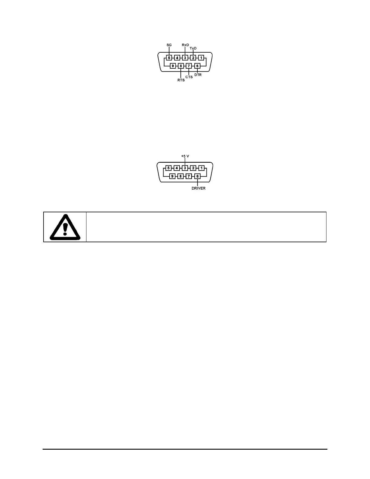
Figure 5: RS232 Pin Assignment
2. Connect the cable to the remote terminal and to the RS232C port at the back of the
attenuator.
Driver Pin Assignment
The driver pin assignment is shown in Figure 6.
Figure 6: Driver Pin Assignment
Caution
Do not exceed 100 mA.
Checking Optional Connections
The attenuator can include an optional coupler or switch. If it does:
1. Ensure that the connections to the coupler or switch are appropriate.
Artisan Technology Group - Quality Instrumentation ... Guaranteed | (888) 88-SOURCE | www.artisantg.com
 Loading...