18
Figure 21 – Transformer rewiring
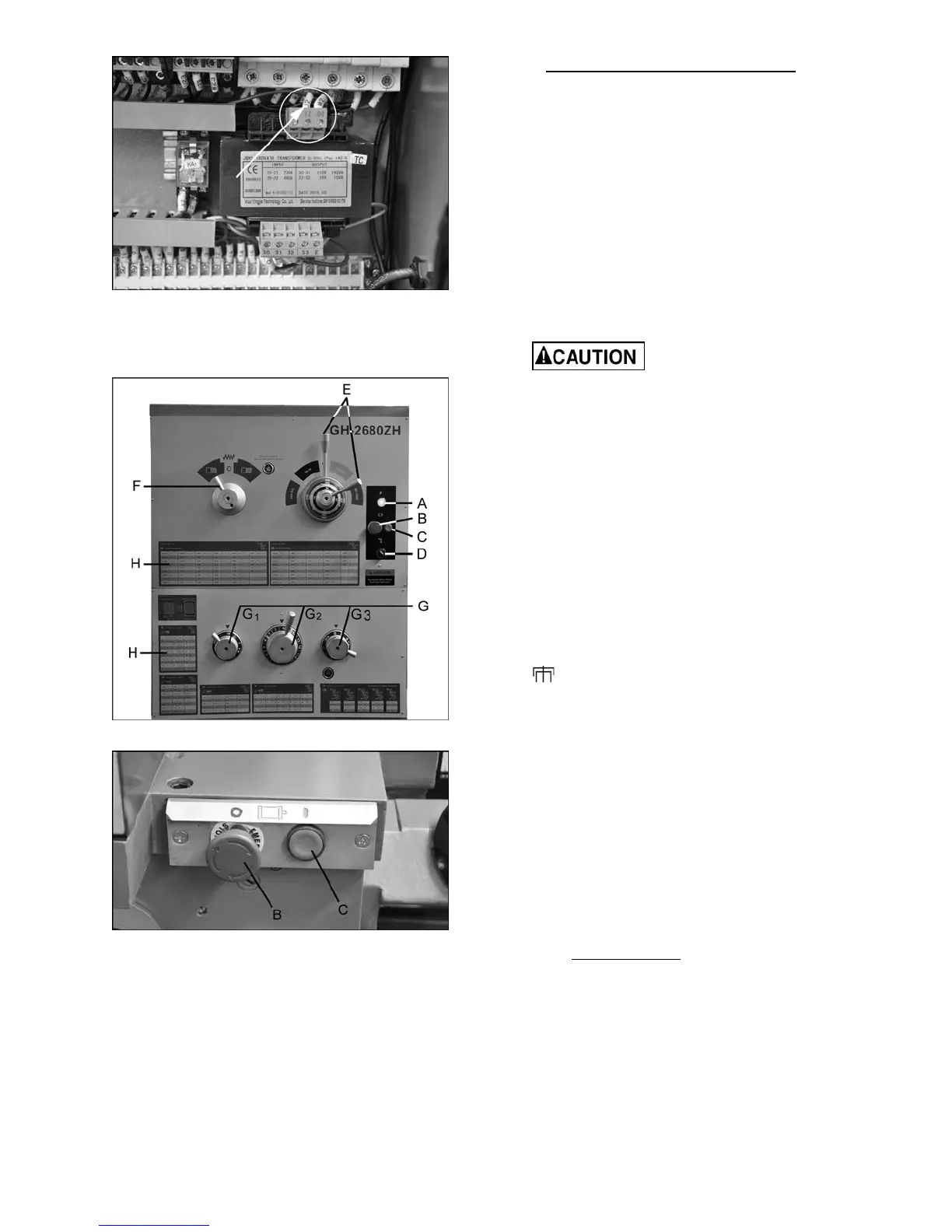
11.0 Basic Controls
Figure 22 – Headstock Controls
Figure 23 – Alternate controls
1. Control Panel: Located on front of headstock.
An abbreviated control panel is also mounted
to front of carriage.
• Power Indicator Light (A, Figure 22).
Illuminates whenever lathe is receiving
power.
• Emergency Stop Button (B, Figure 22 and
23). Shuts down all machine functions.
NOTE: Lathe will still have power. Twist
button clockwise to reset.
• ON Button (C, Figure 22 and 23). Activates
motor.
• Coolant On-Off Switch (D, Figure 22).
Activates coolant pump.
2. Speed Selection Levers (E, Figure 22):
Located on front of headstock. Move levers left
or right to desired spindle speed, according to
accompanying chart on the dial.
3. Feed Direction Lever (F, Figure 22): Located
on front of headstock. Moving the lever
changes direction of feed. Center position is
neutral.
Do not move feed direction
lever while machine is running.
4. Thread Pitch and Feed Selector Levers (G,
Figure 22): Located on front of headstock, are
used conjunctively to set up for threading or
feeding, according to the accompanying chart
(H).
Lever G
1
is used to control/change between
the different thread styles, and is also used for
altering the feed setting.
The symbols on the dial are identified as
follows:
mm = metric threads
IN = inch threads
MP = module pitch
DP = diametral pitch
= when this position is selected, the
input shaft of the gearbox is directly
connected to the lead screw, and will
bypass the gearbox.
This function is available for cutting special
thread forms or nonstandard thread forms,
which are not covered by the standard
gearbox drive train set-up.
Note: Control dial G
3
must be set to position
○ for this operation.
Example: The current standard set of gears
installed with the machine are 82, 97, and
81. This will give a thread pitch equal to
0.506” (12.857mm).
Calculating pitch:
P=(82/97) x (97/81) = 0.6061” (12.857mm)
2
Nonstandard threads are attained by
changing gears in the gear train, based on
this calculation.
Lever G
2
selects the pitch of the thread and the
feed/revolution.
Lever G
3
doubles the thread pitch or
feeddependent on the following positions:
 Loading...