23
Figure 35– Saddle sliding plate adjustment
Figure 36 – Gib adjustments, slide and rest
Compound Rest – Gib screws are located at front
and rear of the compound rest (C, Figure 36). To
adjust, use the same method as for the Cross
Slide.
Half Nut – Gib screws are located on the right side
of the apron (D, Figure 37). Loosen the jam nuts
and rotate the screws clockwise until any backlash
is corrected. Then retighten nuts.
Figure 37 – Half Nut gib adjustment
13.3 Tailstock Adjustments
The tailstock can be offset to cut shallow tapers up
to 5° angle. See Figure 38.
1. Loosen tailstock in position by lowering locking
handle (A).
2. Loosen socket head cap screw (B).
3. Alternately loosen and tighten front and rear
screws (C). (only front screw shown.)
The scale (D) on the end of the tailstock indicates
amount of offset, and helps when re-centering.
Figure 38 – Tailstock adjustments
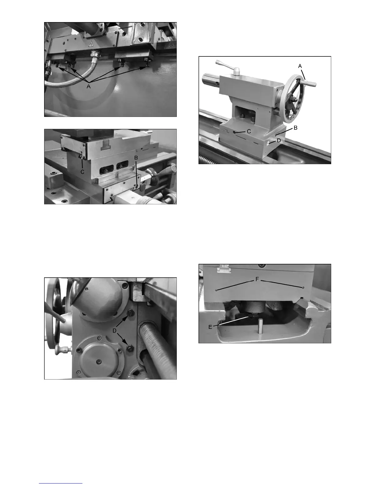
If the clamping force needs to be adjusted, use the
hex nut (E, Figure 39).
When the clamping lever is released, the tailstock
“floats” upward approximately 0.05 to 0.15mm from
the bed ways through four elastically supported
bearings, which allows easy sliding of the tailstock.
The float amount of these bearings can be
adjusted by turning the set screws (F, Figure 39) at
either end. IMPORTANT: This is a sensitive
adjustment. Always clamp the tailstock to the bed
before turning these set screws, to ensure rigidity
and prevent the bearings from crashing.
Figure 39 – Tailstock bearing adjustment
13.4 Gap Section
1. To remove the gap section (A, Figure 40),
remove four socket head bolts (B) and two
socket bolts at the ends of the rails (C).
2. Remove the two tapered alignment pins (D) by
placing the provided gap bridge pin driver (E)
over them and threading the screw (E
1
) down
into them, until the pins are loosened enough
to be pulled out.
3. Remove the gap section.
 Loading...