24
Figure 40 – Gap section
To reinstall the gap section:
4. Clean the bottom and the ends of the gap
section thoroughly.
5. Set gap section in place and align the ends.
6. Insert the tapered pins into their holes through
the gap and into the lathe bed.
7. Reinstall the six bolts (B/C), and tighten
alternately until all are snug. Make sure gap
remains aligned with the ways while tightening
the screws.
13.5
Belt Adjustment and Replacement
The belts should be inspected periodically. New
belts have a tendency to stretch slightly after a
short period of use; and prolonged use will require
that they be tightened to compensate for normal
wear.
NOTE:If a worn, cracked or frayed belt needs
replacing, replace all three as a matched set.
To adjust or replace belts:
1. Disconnect machine from power source.
2. Open end gear cover, remove lower rear cover
and lower side cover. This will expose the
motor and v-belts.
3. Loosen upper hex nut (A, Figure 41). Place
scrap piece of wood under motor to act as
lever. Lift motor up and block temporarily.
4. Remove belts. Install new belts onto pulleys.
5. Lift up on motor and remove temporary
blocking.
6. Tension belts by loosening lower nut (B,
Figure 41) and tightening down upper nut (A,
Figure 41) until light finger pressure causes
approximately 3/4” deflection on each belt.
7. Install covers and connect lathe to the power
source.
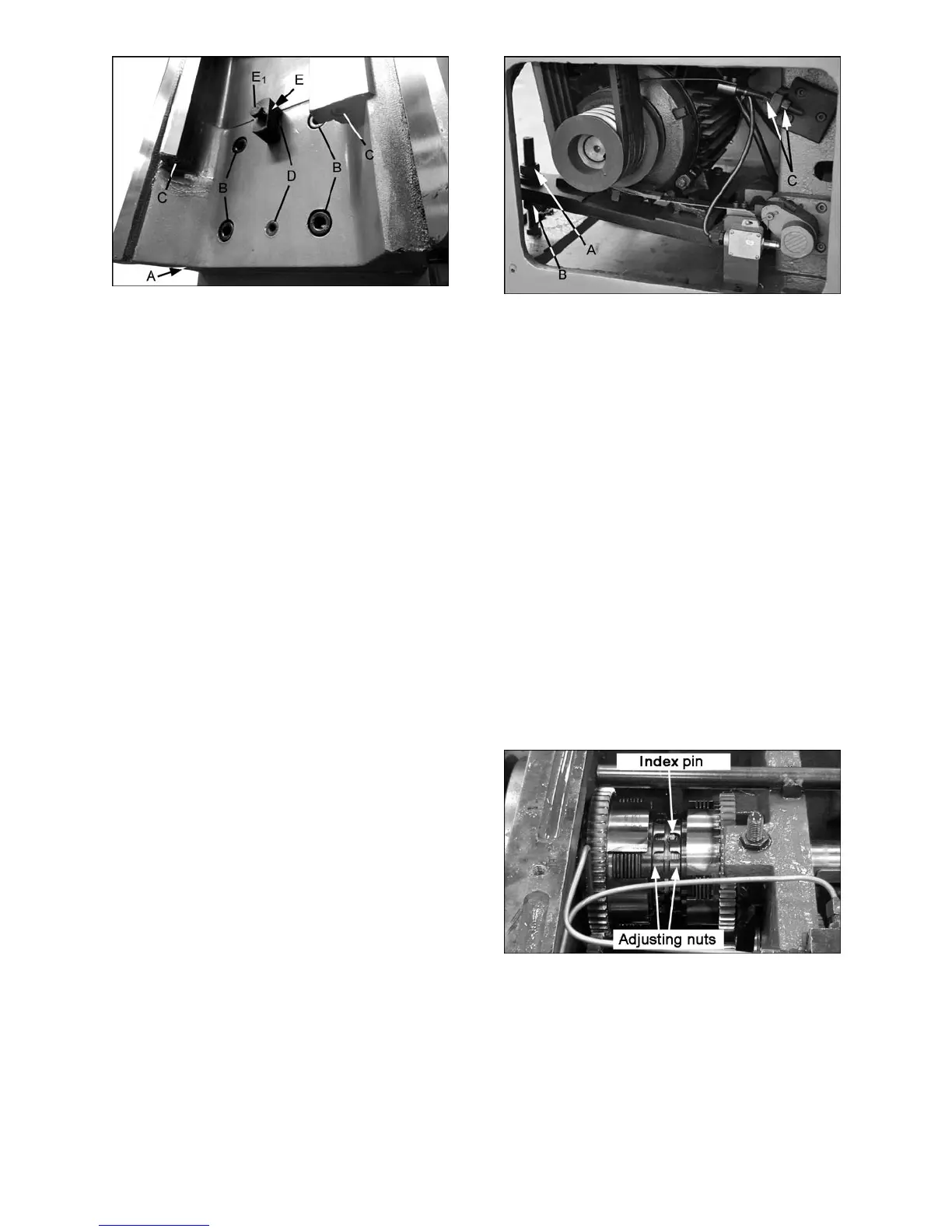
Figure 41 – Belt and brake strap adjustment
13.6 Brake Strap
After the clutch is disengaged, the main drive can
be stopped by the brake. If the spindle does not
stop rapidly, the brake strap may need adjustment.
Use the two adjusting nuts (Figure 41) to tighten
the strap. Do not overtighten the strap, which can
cause it to distort.
13.7 Friction Clutch Adjustment
The lathe operates on a centralized gear drive. The
power of the main motor is transferred through v-
belts to an axle, then through a multi-disc friction
clutch and various gear pairs to the spindle. The
spindle’s forward and reverse motion is controlled
by the clutch; it also provides an overload
protection.
The clutch must be in proper adjustment to ensure
normal working of the spindle. If the clutch is too
loose, its efficiency is reduced and it may slip or
cause heat build-up; if too tight, it becomes difficult
to operate the spindle direction control lever and
the clutch will not properly engage.
Figure 42 – Spindle Clutch Adjustment
 Loading...