20
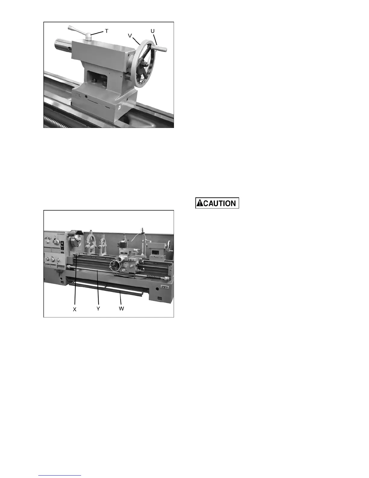
Figure 26 – Tailstock controls
16. Tailstock Quill Clamping Lever (T, Figure
26): Rotate clockwise to lock the sleeve.
Rotate counterclockwise to unlock.
17. Tailstock Clamping Lever (U, Figure 26): Lift
up to lock. Push down to unlock.
18. Tailstock Quill Traverse Handwheel (V,
Figure 26): Rotate clockwise to advance the
quill and counterclockwise to retract it. Fully
retract it to eject a center or drill chuck.
Figure 27 – Other controls
19. Foot Brake (W, Figure 27): For emergency
shutdown of all lathe functions. The connecting
rod mechanism is in the bed stand, and
activates a brake strap at the main motor.
(Caution: Lathe still has power.)
The foot brake is not intended for normal
stopping of the lathe. Overuse can result in
hastened wear of brake parts.
20. Manual Carriage Stop (X, Figure 27): Can be
used during manual feed operation to limit
carriage travel. NOTE: It is not intended to
stop the carriage during automatic feed. The
carriage stop can be repositioned along the
bed by loosening the two screws underneath
the stop.
21. Travel Setting Rod (Y, Figure 27): Up to six
pre-set configurations are possible for
repetitive operations, without having to re-
position the stops each time. Use the knurled
knob at the right end of the rod to set the rod
at one of six positions shown on the dial. Then
move the desired number of eccentric stops
into position for that particular operation and
tighten them securely to the rod with the
screws beneath them. When the apron trip
lever contacts a stop, the clutch will
disengage.
12.0 Operation
The operator should consult shop manuals such as
“Machinery’s Handbook” for cutting speeds and
feeds appropriate to specific workpieces. Correct
feed depends upon the material to be cut, cutting
operation, tool type, chucking rigidity, depth of cut,
and desired surface quality.
IMPORTANT: Allow a break-in period for the new
lathe so that gears and bearings can adapt; do not
run the lathe above 560 RPM for the first six hours
of operation.
The following points must be
observed when operating the lathe:
• Never turn any handles or levers when the
spindle is at high speed.
• Change spindle speed only after the spindle
stops.
• Change feed rate only when the spindle is at
low speed or is stopped.
• Never exceed the maximum speed limitation of
the work holding device.
• Before starting the spindle, always verify that
the oil pump is working (there should be oil in
the sight glass on the front of the headstock).
• Before starting spindle, check that each handle
or lever is at correct position to ensure normal
engagement of the gears. The spindle
direction control lever should be at neutral
position.
• If the brake becomes ineffective, turn off the
machine and adjust the brake immediately.
Never reverse the friction clutch for braking.
• When operating spindle direction control lever,
always turn it to correct position; never use
“pre-position” for cutting at a reduced speed.
• Jaw teeth and scroll must be fully engaged, to
prevent the jaws from breaking and being
thrown from the chuck (see Figure 28).
 Loading...