SECTION 3 - MACHINE OPERATION
31215821 3-31
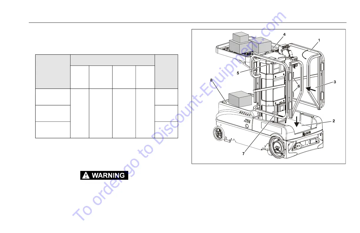
3.11 PLATFORM CONFIGURATION
Platform Lanyard Anchorage Point
Attach fall restraint lanyard to lanyard anchorage point on lower
platform railing. (Refer to item 7 on Figure 3-11.)
ATTACH THE LANYARD TO THE AUTHORIZED LANYARD ANCHORAGE POINT IN
THE PLATFORM. FOR FURTHER INFORMATION REGARDING FALL PROTEC-
TION REQUIREMENTS ON JLG PRODUCTS, CONTACT JLG.
Table 3-3. Platform Maximum Capacity
SPECIFICATION
MAXIMUM CAPACITY
Max.
Wind
Speed
Platform
Load
Manual
Material
Tray Load
Power
Material
Tray Load
Carry
Deck
ANSI/CSA
(Indoor Use Only)
352 lb
(160kg)
254 lb
(115kg)
198lb
(90kg)
254 lb
(115kg)
0 mph
(0 m/s)
CE
(Indoor Use Only)
0 m/s
Australia
(Indoor Use Only)
0 m/s
Figure 3-11. Standard Platform
1. Operators Platform
2. Platform Load (Operator)
3. Platform Swing-In Entry Gate
4. Material Handling Tray
5. Storage Hook
6. Ext. Cord Wrap Hooks
7. Lanyard Attach Point
8. Hood (Carry Deck)
To order go to Discount-Equipment.com