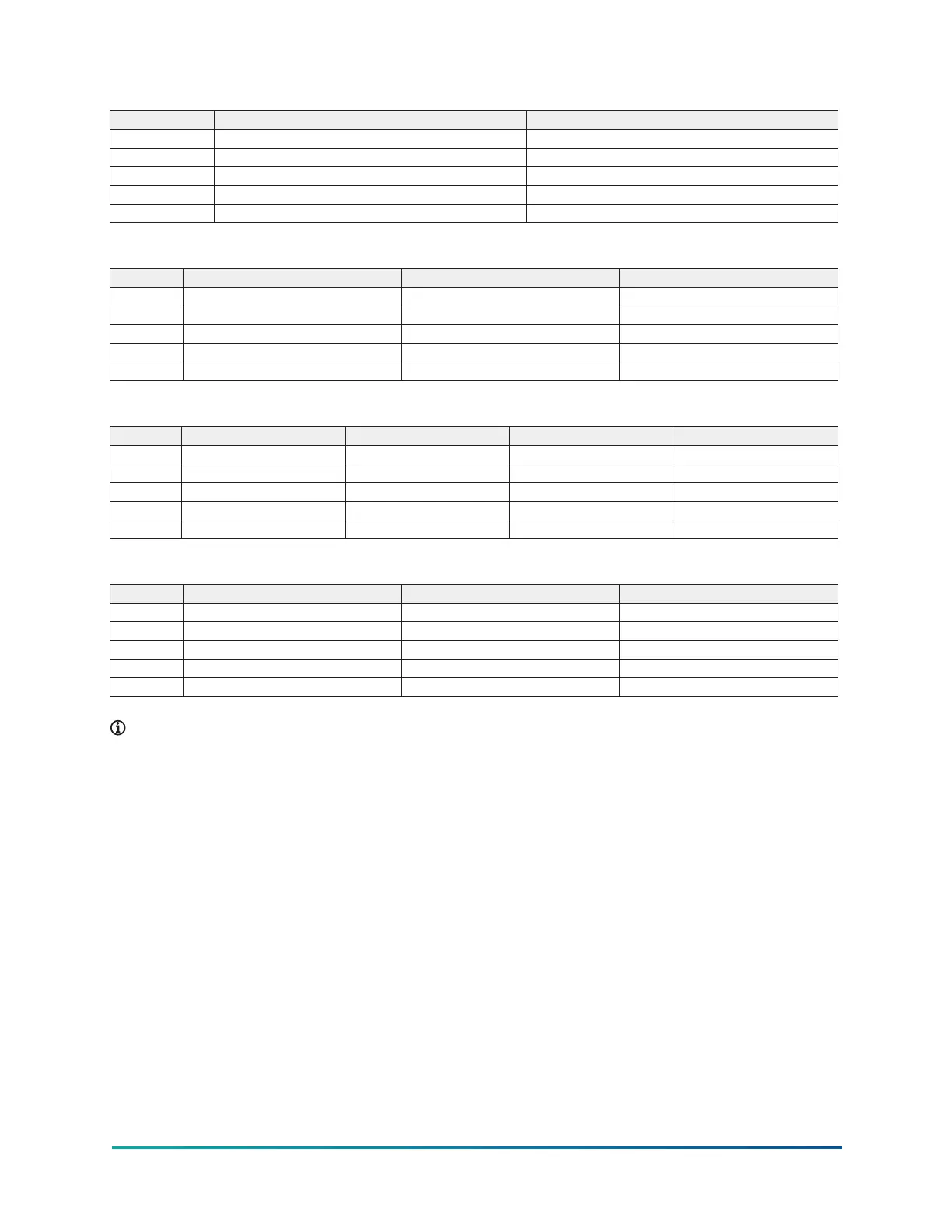
Table 17: Q6 compressor, evaporator - condenser shell codes
Series E–E (mm) F–F (mm)
A 2,134 2,134
B 2,515 2,515
C 495 495
D 445 445
E 3,658 4,877
Table 18: P7, Q7 compressor, evaporator - condenser shell codes
Series E–E (mm) E–I (mm) F–F (mm)
A 1,880 2,178 1,880
B 2,299 2,642 2,299
C 495 495 495
D 445 594 445
E 3,658 3,658 4,877
Table 19: P8 compressor, evaporator - condenser shell codes
Series E–E (mm) F–F (mm) G–G (mm) H–H (mm)
A 2,108 2,108 2,299 2,299
B 3,200 3,200 3,327 3,327
C 610 610 641 641
D 445 445 508 508
E 3,658 4,877 3,658 4,877
Table 20: P9 compressor, evaporator - condenser shell codes
Series H–F (mm) J–J (mm) L–L (mm)
A 2,108 2,299 2,299
B 3,124 3,264 3,264
C 610 641 641
D 445 508 508
E 4,877 3,658 4,877
Note:
1. All dimensions are approximate.
2. For compact waterboxes, see Figure 14, determine overall unit length by adding
waterbox depth to tube sheet length.
3. Water nozzles can be located on either end of unit. Add 1/2 in. (13 mm) to nozzle length
for flanges connections.
4. To determine overall height, add 7/8 in. (22 mm) for isolators.
5. Use of motors with motor hoods may increase overall unit dimensions.
35Model YK (Style G) Centrifugal Liquid Chiller

 Loading...


