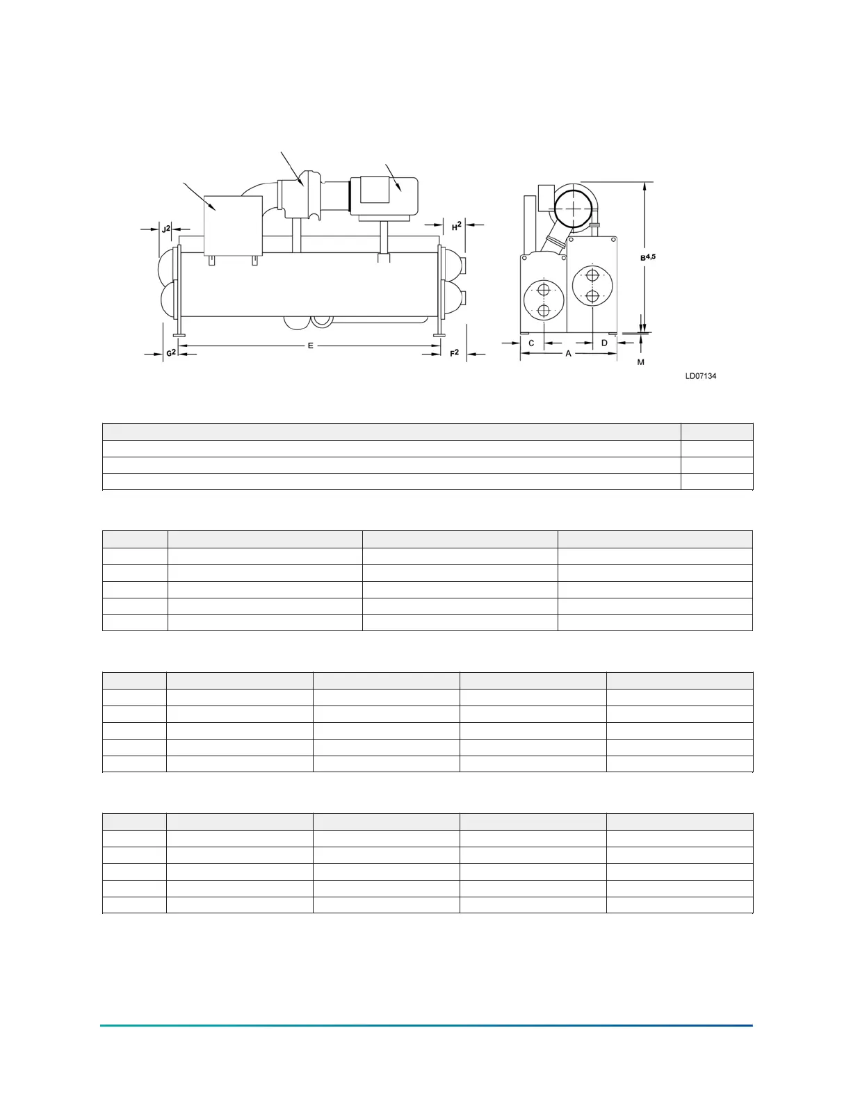
P and Q compressor units (standard)
Figure 13: P and Q compressor unit dimensions (ft in.)
Table 5: Additional operating height clearance to floor
Type of chiller mounting M (in.)
Neoprene pad isolators 1 3/4
Spring isolators 1 in. deflection 1
Direct mount 3/4
Table 6: Q3 compressor, evaporator - condensor shell codes
Series A–A C–C D–D
A 5 ft 1 in. 5 ft 6 in. 5 ft 6 in.
B 7 ft 0 in. 7 ft 3 3/4 in. 7 ft 3 3/4 in.
C 1 ft 3 1/2 in. 1 ft 5 1/2 in. 1 ft 5 1/2 in.
D 1 ft 3 in. 1 ft 3 1/2 in. 1 ft 3 1/2 in.
E 12 ft 0 in. 12 ft 0 in. 16 ft 0 in.
Table 7: Q4 compressor, evaporator - condenser shell codes
Series C–B C–C D–D E–E
A 6 ft 4 3/4 in. 5 ft 6 in. 5 ft 6 in. 7 ft 0 in.
B 7 ft 11 3/8 in. 7 ft 2 1/2 in. 7 ft 2 1/2 in. 7 ft 8 1/2 in.
C 1 ft 5 1/2 in. 1 ft 5 1/2 in. 1 ft 5 1/2 in. 1 ft 7 1/2 in.
D 1 ft 8 7/8 in. 1 ft 3 1/2 in. 1 ft 3 1/2 in. 1 ft 5 1/2 in.
E 12 ft 0 in. 12 ft 0 in. 16 ft 0 in. 12 ft 0 in.
Table 8: Q5 compressor, evaporator - condenser shell codes
Series C–C D–D E–E F–F
A 5 ft 6 in. 5 ft 6 in. 7 ft 0 in. 7 ft 0 in.
B 7 ft 10 5/8 in. 7 ft 10 5/8 in. 8 ft 5 1/2 in. 8 ft 5 1/2 in.
C 1 ft 5 1/2 in. 1 ft 5 1/2 in. 1 ft 7 1/2 in. 1 ft 7 1/2 in.
D 1 ft 3 1/2 in. 1 ft 3 1/2 in. 1 ft 5 1/2 in. 1 ft 5 1/2 in.
E 12 ft 0 in. 16 ft 0 in. 12 ft 0 in. 16 ft 0 in.
Model YK (Style G) Centrifugal Liquid Chiller32

 Loading...


