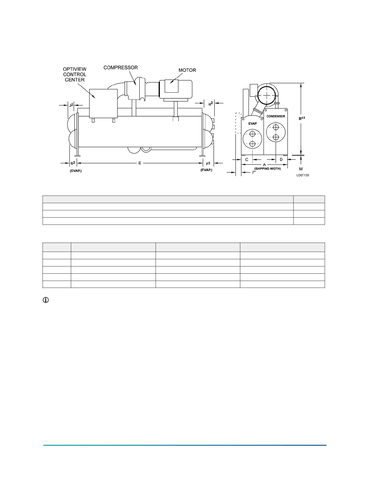
H compressor units (metric)
Figure 16: H compressor unit dimensions (mm)
Table 23: Additional operating height clearance
Type of chiller mounting M (mm)
Neoprene pad isolators 44
Spring isolators 25mm deflection 25
Direct mount 19
Table 24: H9 compressor evaporator - condenser shell codes
I-K, K–K (mm) K–O (mm) M–M (mm)
A 2,299 2,673 2,616
B 3,150 3,242 3,315
C 641 641 724
D 508 695 584
E 4,267 4,267 4,267
Note:
1. All dimensions are approximate.
2. For compact waterboxes, see Figure 16, determine overall unit length by adding
waterbox depth to tube sheet length.
3. Water nozzles can be located on either end of unit. Add 1/2 in. (13 mm) to nozzle length
for flanges connections.
4. To determine overall height, add 7/8 in. (22 mm) for isolators.
5. Use of motors with motor hoods may increase overall unit dimensions.
37Model YK (Style G) Centrifugal Liquid Chiller

 Loading...


