Associated literature
Table 1: List of associated literature
Manual description Form number
Installation checklist and start-up request 160.75-CL1
Unit start-up checklist 160.75-CL2
Installation and reassembly - unit 160.75-N3
Installation - MV VSD - 2300 VAC – 6600 VAC 160.00-N6
Installation - MV VSD - 10 kV – 13.8 kV 160.00-N8
Wiring Diagrams - field connections - unit-mounted SSS, MV SSS, or remote mounted MV SSS, MV EMS 160.75-PW1
Wiring diagrams - field connections - remote mounted MV SSS 160.75-PW2
Wiring diagrams - field connections - remote mounted MV VSD 160.75-PW3
Wiring diagrams - field connections - LV VSD 160.54-PW6
Wiring diagrams - OptiView Control Center and EMS 160.75-PW5
Wiring diagrams - OptiView Control Center and EMS with the LTC I/O Board 160.75-PW7
Wiring diagrams - OptiView Control Center and SSS, LV VSD, MV VSD 160.75-PW6
Wiring diagrams - OptiView Control Center and SSS, LV VSD, MV VSD with the LTC I/O board 160.75-PW8
Wiring diagrams - field control modifications 160.75-PW4
Unit operation and maintenance 160.75-O1
Operation OptiView panel 160.54-O1
Operation - variable speed drive - TM model 160.00-O1
Operation and maintenance - solid state starter (Mod "B") 160.00-O2
Operation - variable speed drive - VSD and LVD model 160.00-O4
Operation - variable speed drive - HYP model 160.00-O10
Operation - floor mounted MV SSS, manufactured before 2007 160.00-O5
Operation - floor mounted MV SSS, manufactured after 2007 160.00-O5.1
Operation - unit mounted MV SSS 160.00-O7
Operation - MV VSD - 2300 VAC – 6600 VAC 160.00-O6
Operation - MV VSD - 10 kV – 13.8 kV 160.00-O8
Service policy - shipping damage claims 50.15-NM
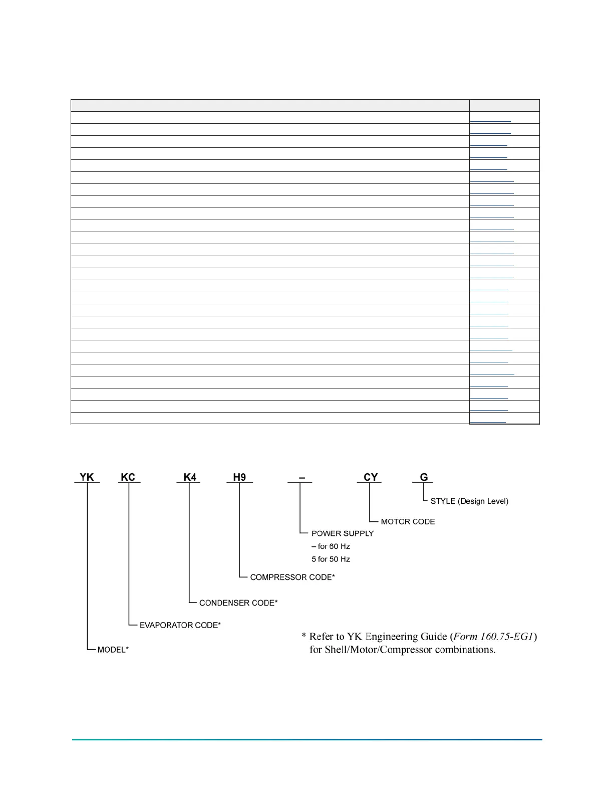
Nomenclature
7Model YK (Style G) Centrifugal Liquid Chiller

 Loading...


