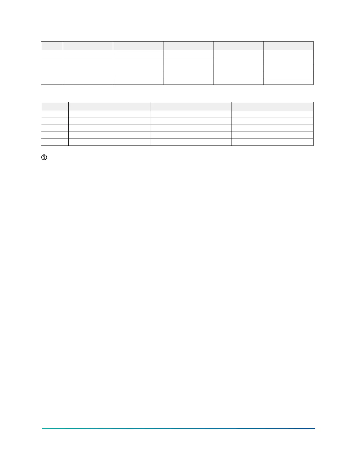
Table 29: K4 compressor, evaporator - condenser shell codes
R–R S–S S–V X–T X–X
A 9 ft 9 in. 9 ft 9 in. 10 ft 3 in. 10 ft 10 in. 11 ft 3 in.
B 11 ft 11 in. 11 ft 11 in. 12 ft 4 in. 12 ft 4 in. 12 ft 4 in.
C 2 ft 8 in. 2 ft 8 in. 2 ft 8 in. 2 ft 11 1/2 in. 2 ft 11 1/2 in.
D 2 ft 3 1/2 in. 2 ft 3 1/2 in. 2 ft 5 1/2 in. 2 ft 5 1/2 in. 2 ft 8 in.
E 16 ft 0 in. 18 ft 0 in. 18 ft 0 in. 16 ft 0 in. 16 ft 0 in.
Table 30: K7 compressor, evaporator - condenser shell codes
W–W Z–Y Z–Z
A 10 ft 3 in. 12 ft 7 in. 11 ft 3 in.
B 12 ft 2 in. 14 ft 1 5/8 in. 12 ft 10 in.
C 2 ft 8 in. 2 ft 11 1/2 in. 2 ft 11 1/2 in.
D 2 ft 5 1/2 in. 3 ft 4 in. 2 ft 8 in.
E 22 ft 0 in. 18 ft 0 in. 18 ft 0 in.
Note:
1. All dimensions are approximate.
2. For compact waterboxes, see Figure 17, determine overall unit length by adding
waterbox depth to tube sheet length.
3. Water nozzles can be located on either end of unit. Add 1/2 in. (13 mm) to nozzle length
for flanges connections.
4. To determine overall height, add 7/8 in. (22 mm) for isolators.
5. Use of motors with motor hoods may increase overall unit dimensions.
39Model YK (Style G) Centrifugal Liquid Chiller

 Loading...


