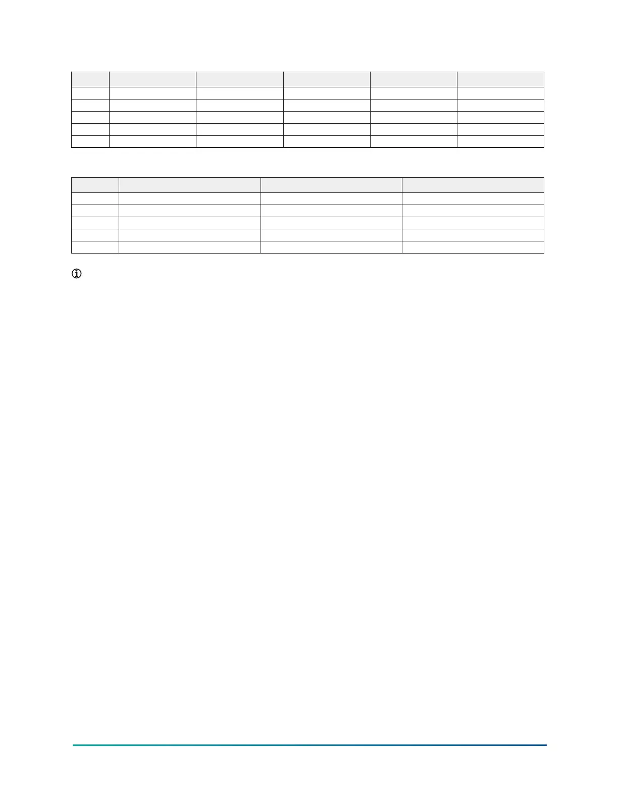
Table 35: K4 compressor, evaporator - condenser shell codes
R–R (mm) S–S (mm) S–V (mm) X–T (mm) X–X (mm)
A 2,972 2,972 3,124 3,302 3,429
B 3,632 3,632 3,759 3,759 3,759
C 813 813 813 902 902
D 699 699 749 749 813
E 4,877 5,486 5,486 4,877 4,877
Table 36: K7 compressor, evaporator - condenser shell codes
W–W (mm) Z–Y (mm) Z–Z (mm)
A 3,124 3,835 3,429
B 3,708 4,308 3,912
C 813 902 902
D 749 1,016 813
E 6,706 5,486 5,486
Note:
1. All dimensions are approximate.
2. For compact waterboxes, see Figure 18, determine overall unit length by adding
waterbox depth to tube sheet length.
3. Water nozzles can be located on either end of unit. Add 13 mm (1/2 in.) to nozzle length
for flanges connections.
4. To determine overall height, add 22 mm (7/8 in.) for isolators.
5. Use of motors with motor hoods may increase overall unit dimensions.
41Model YK (Style G) Centrifugal Liquid Chiller

 Loading...


