JOHNSON CONTROLS
31
SECTION 2 - INSTALLATION
FORM 160.75-N1
ISSUE DATE: 4/30/2014
2
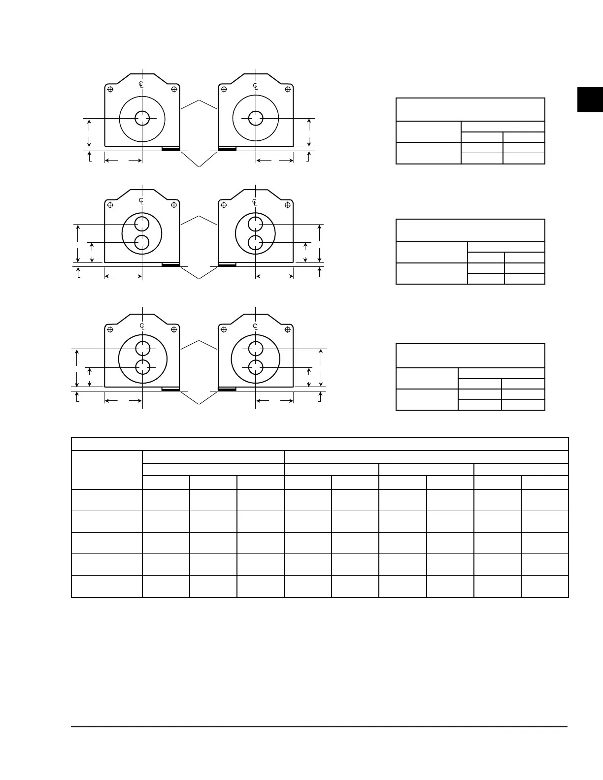
FIGURE 19 - DIMENSIONS – EVAPORATOR COMPACT WATERBOXES A THRU L EVAPORATORS
CC
COMPRESSOR END
FLOOR LINE
MOTOR END
AA
M
AA
M
AH
EVAP.EVAP.
FRONT
OF
UNIT
M
M
CC
FLOOR LINE
COMPRESSOR END
MOTOR END
COMPRESSOR END
MOTOR END
B
C
J
K
EVAP.EVAP.
FRONT
OF
UNIT
BB BB
DD
DD
MM
CC
FLOOR LINE
F
G
N
P
EVAP.EVAP.
FRONT
OF
UNIT
BB
DD
BB
DD
EVAPORATORS – COMPACT WATERBOXES – A THRU L EVAPORATORS - FT - IN (MM)
NOZZLE
ARRANGEMENTS
NUMBER OF
PASSES
EVAPORATOR
IN OUT
1
A H
H A
NOZZLE
ARRANGEMENTS
NUMBER OF
PASSES
EVAPORATOR
IN OUT
2
C B
K J
NOZZLE
ARRANGEMENTS
NUMBER OF
PASSES
EVAPORATOR
IN OUT
3
G N
P F
COMPACT WATERBOXES – 150 PSI ROUND
CONDENSER
SHELL CODE
NOZZLE PIPE SIZE IN (MM) EVAPORATOR NOZZLE DIMENSIONS FT-IN (MM)
NUMBER OF PASSES 1-PASS 2-PASS 3-PASS
1 2 3 C AA
5
BB
5
DD
5
BB
5
DD
5
A
8"
(203)
6"
(152)
4"
(101)
1'-3 1/2"
(394)
1'-10"
(559)
1'-2"
(356)
2'-6"
(762)
1'-2"
(356)
2'-6"
(762)
C,D
10"
(254)
8"
(203)
6"
(152)
1'-5 1/2"
(445)
2'-0"
(610)
1'-3"
(381)
2'-9"
(838)
1'-3"
(381)
2'-9"
(838)
E,F
14"
(355)
10"
(254)
8"
(203)
1'-7"
(483)
2'-2"
(660)
1'-4"
(406)
3'-0"
(914)
1'-4"
(406)
3'-0"
(914)
G,H
14"
(355)
10"
(254)
8"
(203)
2'-0"
(610)
2'-3 1/2"
(699)
1'-3 1/2"
(394)
3'-3 1/2"
(1,003)
1'-3 1/2"
(394)
3'-3 1/2"
(1,003)
I,J,K,L
16"
(406)
12"
(305)
10"
(254)
2'-1 1/4"
(641)
2'-6"
(762)
1'-5"
(432)
3'-7"
(1092)
1'-5"
(432)
3'-7"
(432)
LD07598a
NOTES:
1. Standard water nozzles are furnished as welding stub-outs with grooves, allowing the option of welding, anges, or use of Victaulic
couplings. Factory-installed, class 150 (ANSI B16.5, round slip-on, forged carbon steel with 1/16" raised face), water anged nozzles are
optional (add 1/2" to nozzle length). Companion anges, nuts, bolts, and gaskets are not furnished.
2. One-, two- and three-pass nozzle arrangements are available only in pairs shown and for all shell codes. Any pair of evaporator nozzles
may be used in combination with any pair of condenser nozzles.
3. Evaporator and condenser water must enter the waterbox through the bottom connection to achieve rated performance.
4. Connected piping should allow for removal of compact waterboxes for tube access and cleaning.
5. Add dimension "M" as shown on the unit dimensions page for the appropriate isolator type.
6. Standard 150 PSI design pressure boxes shown.

 Loading...