ZFR1800 Series Wireless Field Bus System Technical Bulletin38
b. If any sensors have not come online, initiate a signal strength test with the
associated ZFR1811 Router. Press and hold the manual occupancy override
button on the WRZ Series Sensor for 5 seconds or more, then release the
button. After you release the button, the signal strength code displays.
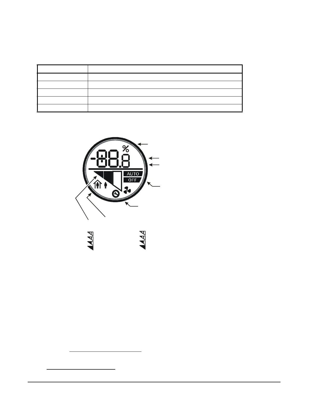
On LCD models, the signal strength is shown on the display on the face of the
sensor (callout in Figure 14).
For more information on the ZCT, refer to the Using the ZFR Checkout Tool
(ZCT) chapter of the Controller Tool Help (LIT-12011147).
7. Verify the MS/TP wired trunk communications.
a. Connect all of the ZFR1810 coordinators and other devices to the MS/TP
wired trunk.
b. If an NAE is available, log on to the NAE and check that all controllers and
sensors are online and updating. If no NAE is available, use the Point
Schedule utility.
Also see Verifying Wireless Operation.
8. Continue with your normal system commissioning procedure. Also see
Commissioning the WEFCs.
Table 8: WRZ Sensor to ZFR1811 Router Wireless Signal Strength
Flashes Signal Strength
3 Excellent/Sensor has joined network
2 Good/Sensor has joined network
1 Weak/Sensor has joined network
0 None/Sensor has not joined network
Fast Flash Rate (8) Unable to locate associated wireless enabled field controller
Figure 14: Sensor LCD (WRZ-MTB, WRZ-STR, WRZ-THB, WRZ-TTB, and WRZ-TTD
Models)
Temperature
FIG:lcd_dsply_RH
Fahrenheit
Temperature
Indicates Loss of Network
Connection When Symbol
is Present
°F
°C
= No Signal
= Weak Signal
= Good Signal
= Excellent Signal
Signal Strength Graph:
= Off
= Low Fan Speed
= Medium Fan Speed
= High Fan Speed
Fan Speed Indication Graph:
Occupied/Unoccupied Mode
low-medium-high)