14
JPK Instruments NanoWizard
®
Handbook Version 2.2
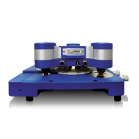
Typical interaction for
an uncoated
hydrophilic cantilever in air
approaching a hard incompressible
hydrophilic surface (e.g. glass or
mica). Hy
drophilic surfaces are
covered with a thin water layer in
ambient conditions. These layers
join when the tip and sample are
close together, forming a capillary
neck between them and hence a
strong adhesion.
Calibration of the cantilever deflection
The deflection of the cantilever spring is directly proportional to the tip-
sample
interaction force, but there are two measurements required to convert the
photodetector signal into a quantitative value of force. The first stage is to calibrate
the distance tha
t the cantilever actually deflects for a certain measured change in
photodetector voltage. This value depends on type of cantilever, but also on the
optical path of the AFM detection laser, and will be slightly different each time the
cantilever is mounte
d in the instrument. Once the deflection of the cantilever is
known as a distance, the spring constant is then needed to convert this value into a
force, using the well-known Hooke's law.
F = - k * x
x = cantilever deflection
(units of distance)
k = spring constant
F = deflection force
A force curve between a plain cantilever tip and a bare hard substrate is used to
determine the sensitivity of the experimental setup. This is a measurement of the
deflection of the tip in nanometers for a given moveme
nt of the detection laser on
the photodetector. The repulsive contact region, where the deflection rises steeply
upwards, is linear for a hard surface and tip. Therefore the software can easily
determine the factor for converting Volts into nanometers.
This measurement can
then be used for calibrating the applied forces when the samples of interest are
investigated. The sensitivity can then also be used to set the oscillation amplitude
in intermittent contact mode as actual nanometers of oscillation.
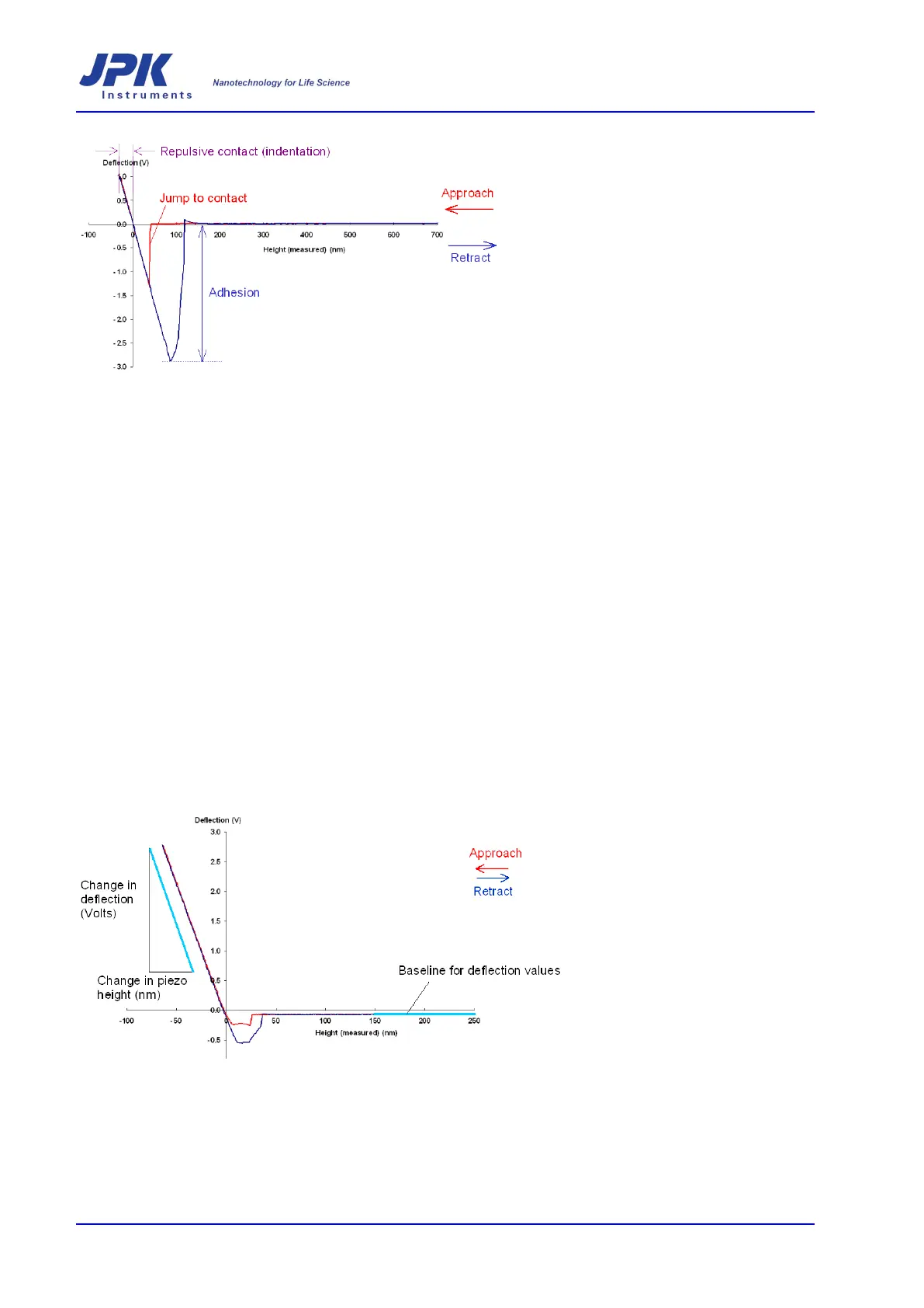
The gradient chosen for sensitivity
measurements and the baseline
offset for the deflection are both
marked on this plot.
Since the hard repulsive interaction
regime is used for the sensitivity
measurement, the force curves ar
e
often actually done at the end of the
experiment to avoid damaging the
tip.
The example above shows the two regimes useful for calibrating the deflection.
When the cantilever is far from the surface, the interaction forces are virtually zero
(the flat
part of the curve on the right hand side). This offset , which may be due to
the initial settings of the equipment, or to thermal drift, should be subtracted from all
the deflection data in order to calculate the true interaction force.
On a hard surface:
Change in cantilever deflection =
change in piezo height