JPK Instruments NanoWizard
®
Handbook Version 2.2a
15
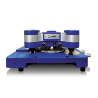
The other linear region, on the left hand side of the plot, is where the tip is resting
on the surface. If the surface is not compressed by the cantilever forces, then the
change in the piezo he
ight (known from the height calibration in nm) is equal to the
cantilever deflection (measured from the photodiode in Volts).
The sensitivity is the conversion
factor (nm true deflection per Volt
measured deflection) needed to
convert the photodiode deflec
tion
into units of length.
The example from above has been
shifted here to give a zero baseline.
The sensitivity (measured from the
curve above as 22 nm/V) has been
used to convert the deflection into
units of length (nm).
The deflection values here a
re now
ready to be converted to units of
Force (N).
Correction of the height for the cantilever deflection
The plot so far has used an x-
axis of the cantilever height directly
measured from the piezo position. For quantitative analysis of indentation
or
stretching, however, the cantilever is obviously deflected from its
equilibrium position. The deflection should be taken into account to extract
the true tip position relative to the surface. The deflection can then be
plotted against the tip-sample sepa
ration, rather than the piezo height.
Now that the deflection is in units of length, it can be subtracted from the
piezo height at each point to correct for the tip position.
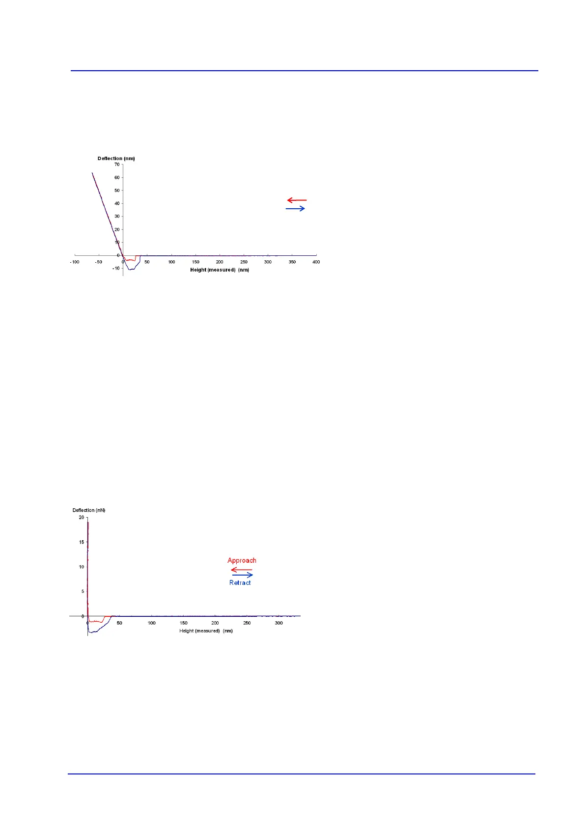
After the sensitivity conversion, the straight line part of the repulsive
int
eraction (left hand side of the curve above) has a gradient of 1, since this
is the basis of the sensitivity calculation. Once the height scale is
corrected, this becomes a vertical line (as seen in the curve below). This is
because the tip-sample separa
tion remains constant at zero, and the action
of the piezo movement merely increases or decreases the force.
The example from above has had
the x-
axis corrected for the tip
deflection. The x-
true tip-sample se
paration, rather
than the piezo height measured
directly.
For quantitative force measurement, the spring constant of the cantilever must be
calibrated, so that the nanometers deflection of the cantilever can be converted into
actual force values. There ar
e various different ways of calibrating spring constants
of cantilevers, depending on the equipment that is available. See Section 4.5
more details. The example above has had the deflection multiplied by
the spring
constant to express the deflection as a force and would now be ready for analysis.
Retract
Approach