Name Specification Shield
(Y/N)
Norm
Power 2 x 1.5 mm
2
Y IEC 60092-352
USB USB Y
Serial
3 x 2 x 0.5 mm
2
(inside cabinets)
3 x 2 x 0.75 mm
2
(ship's cabling)
Y
IEC 61162-2
Serial
2 x 2 x 0.5 mm
2
(inside cabinets)
2 x 2 x 0.75 mm
2
(ship's cabling)
Y IEC 61162-1
Ethernet Ethernet CAT 5e S/FTP Y
Table 3: Connection Cables
1.1.8 Cable Preparation
Cable preparation and cable connections as described in this manual are essential for the correct functioning of the
instrument.
Note There are two type of cable sides (connections): sending cable sides and receiving cable sides. Normally,
the cable shield will be grounded only at the sending side of the cable. For a power cable, this is the power
supply side. For a data cable, this is the Tx side of the cable. For combined Tx/Rx cables, either side can be
grounded, but beware of grounding only one side.
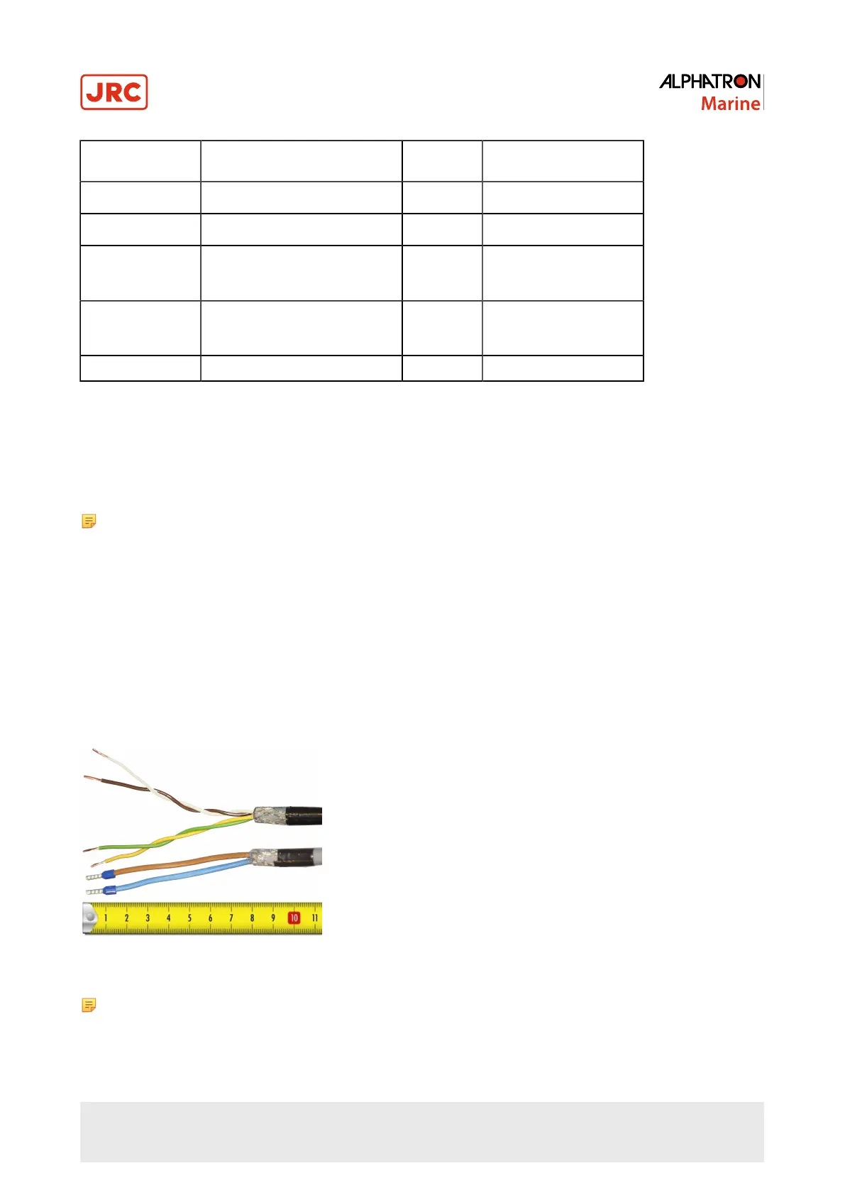
1.1.8.1 Cable Preparation Sending Sides
1. Remove approx. 80 mm of the plastic cable sheath, including the grounding shield.
2. Cut away approx. half of the length of the now visible cable shield and fold the remaining shield back over the cable
sheath.
3. Wrap insulating tape over half of the visible grounding shield.
4. Attach the remaining visible grounding shield to the metal saddle on the rear of the instrument. See Figure 4: Cable
Preparation Sending Cable Sides on page 13.
Figure 4: Cable Preparation Sending Cable Sides
Note Always check the drawing for the correct shielding of signals.
13 | Installation Instructions

 Loading...


