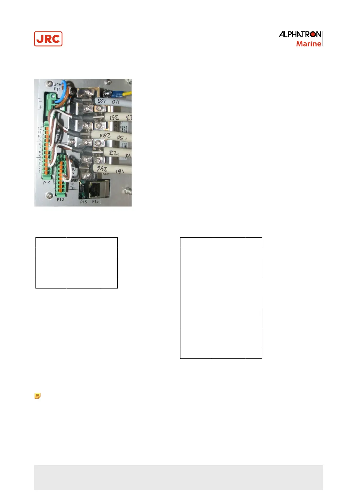
For pin connections, see Figure 10: Serial pin connections on page 17, Table 4: Serial Connector P12 (8 pins) on
page 17 and Table 5: Serial Connector P19 (12 pins) on page 17.
Figure 10: Serial pin connections
1 COM0 IEC 61162-2 Tx+
2 COM0 IEC 61162-2 Tx–
3 COM0 IEC 61162-2 GND
4 COM0 IEC 61162-2 Rx+
5 COM0 IEC 61162-2 Rx–
Table 4: Serial Connector P12 (8 pins)
1 COM1 IEC 61162-1 Tx+
2 COM1 IEC 61162-1 Tx–
3 COM1 IEC 61162-1 Rx+
4 COM1 IEC 61162-1 Rx–
5 COM2 IEC 61162-1 Tx+
6 COM2 IEC 61162-1 Tx–
7 COM2 IEC 61162-1 Rx+
8 COM2 IEC 61162-1 Rx–
9 COM3 IEC 61162-1 Tx+
10 COM3 IEC 61162-1 Tx–
11 COM3 IEC 61162-1 Rx+
12 COM3 IEC 61162-1 Rx–
Table 5: Serial Connector P19 (12 pins)
Note The instrument should always be connected according to the cable diagram. See Electric Diagrams on
page 51. Ensure connection to the correct COM port.
1.1.13 Relay
One relay output is available for legacy alarm monitoring systems without serial ALR connection. This AlphaLine
instrument relay output is located on the 8-pin connector on the following pins. Use the NC (Normally Closed), or NO
(Normally Open) connection depending on the application.
For pin lay out, see Table 6: Relay Connector P12 (8 pins) on page 18.
17 | Installation Instructions
 Loading...


