Chapter 3 INSTALLATION OF THE DISPLAY UNIT
3.8 CONNECTING TO THE GYRO AND ELECTROMAGNETIC LOG (NSK UNIT SETTING)
3-23
3
NSTALLATION MANUAL
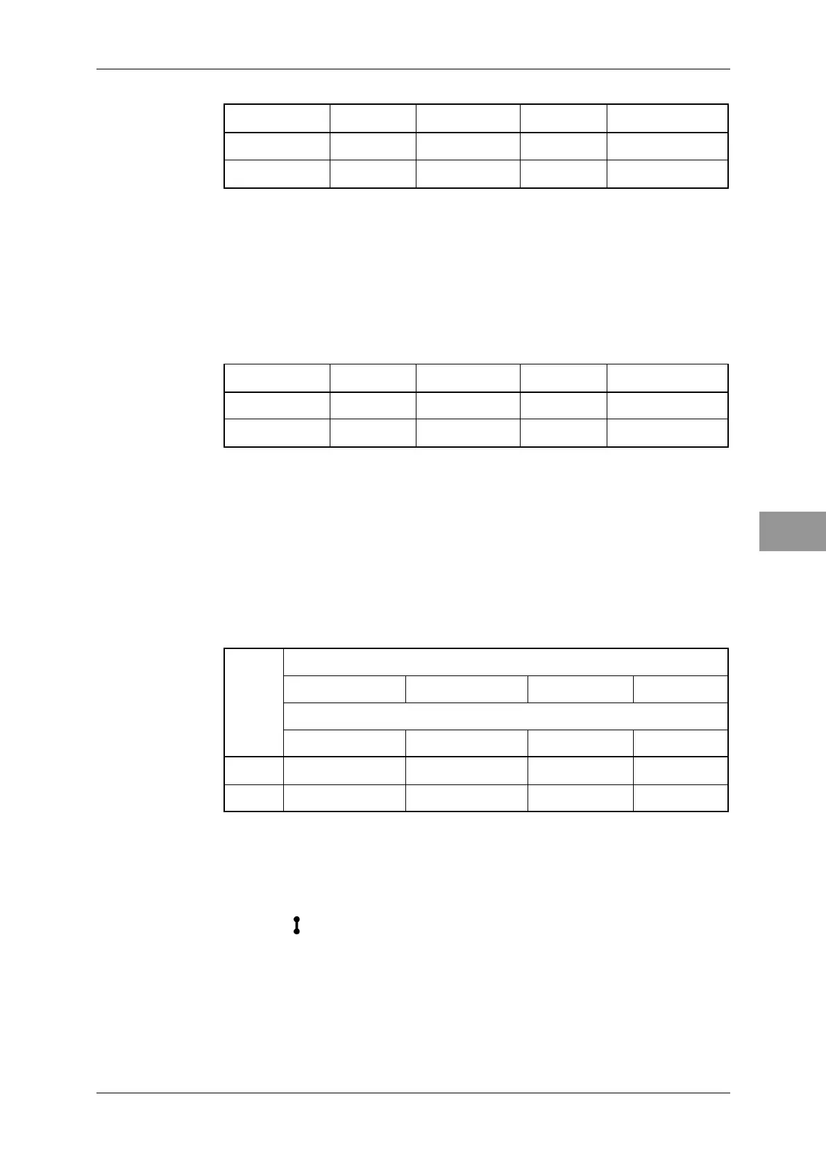
S4-7, 8 ························Set the baud rate when using NMEA.
4800 9600 19200 38400
S4-7 OFF ON OFF ON
S4-8 OFF OFF ON ON
S5:
Make settings for S5 according to the type of gyro compass. Refer to the S5
setting table.
S5-1 ···························Set it according to the particular type of gyro.
Synchro signal ·································· [OFF]
Step signal ······································· [ON]
S5-2, 3 ························Set it according to the gyration ratio.
360X 180X 90X 36X
S5-2 OFF ON OFF ON
S5-3 OFF OFF ON ON
S5-4 ···························Set the gyration direction
Normal (clockwise) ····························· [OFF]
Reverse (counterclockwise) ···················· [ON]
S5-5 ···························Set the log type.
Pulse signal ····································· [OFF]
Synchro signal ·································· [ON]
S5-6 ···························Not used
S5-7, 8 ························Set the log ratio.
Pulse/NM (pulse signal)
800 400 200 100
Gyration/NM (synchro signal)
360X 180X 90X 30X
S5-7 OFF ON OFF ON
S5-8 OFF OFF ON ON
When using the step gyro and the step voltage is 24 VDC or less, set the jumper shown
below.
TB105: Set the level of step gyro.
Indication
side ······························· Normal setting
Side with no indication ························ Step 24 VDC or less
 Loading...


