Chapter 3 INSTALLATION OF THE DISPLAY UNIT
3.8 CONNECTING TO THE GYRO AND ELECTROMAGNETIC LOG (NSK UNIT SETTING)
3-24
2 Connect the gyro signal and the log signal cables to the gyro I/F circuit.
CMJ-304D/E side Connecting device side
TB10 Gyro signal (synchro/step)
TB20 Log signal (synchro/pulse)
Set the speed log signal input to TB20. However, set the pulse type to PULSE
and the synchro type to SYNC . Note that - side is the ground for the pulse
type.
3 Set S1 to [ON].
Reference:
After power-on operation, the switch S5-4 shall be set to [ON] if the radar video and the
indicated value of COURSE (own ship’s true bearing) is reversed.
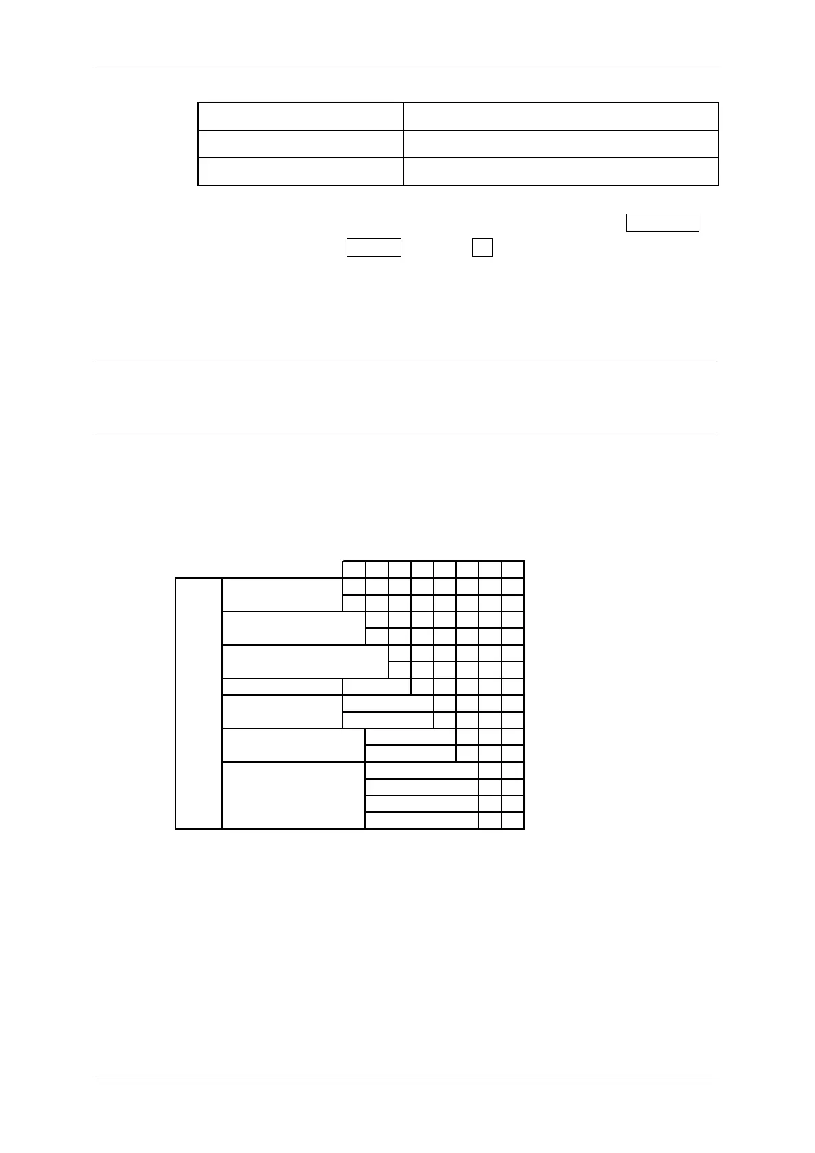
CMJ-304D/E Gyro I/F Setting table
S4 SETTING TABLE
12345678
ON
OFF
ON
OFF
ON
OFF
any
ON
OFF
ON
OFF
OFF OFF
ON OFF
OFF ON
ON ON
HEADING SENSOR
SOURCE
NMEA(HDT/THS)
GYRO SIGNAL
OTHER SETTING
LOG ALARM
GYRO SIMULATOR
LOG SIMULATOR
N.C.
Don't care
GYRO ALARM
TIME
NMEA BAUDRATE
SETTING
5s
0.5s
4800
9600
19200
38400
 Loading...


