89
[II] Sensor Test
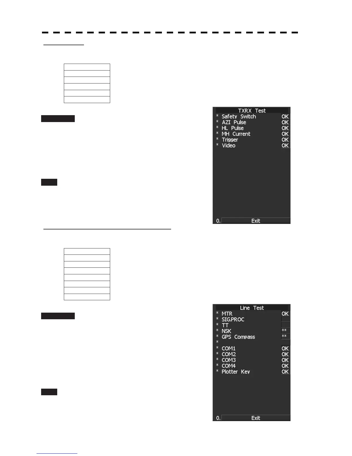
Checks for signals from the antenna.
Safety Switch
Antenna’s safety switch check
AZI Pulse
Antenna rotation signal check
HL Pulse
Heading line signal check
MH Current
Check on the load current of high voltage in the modulator
Trigger
Radar trigger signal check
Video
Radar video check
Procedure 1 Press [2] key while the Self Test menu
is open.
The Sensor Test menu will appear.
When no abnormality is found, OK is displayed.
When an abnormality is found, NG is displayed.
In standby, 㧖㧖 will appear.
Exit 1 Press [RADAR MENU] key.
The menu will be closed.
[III] Check of Communication Lines (Line Test)
Check communication with operational devices and external navigators.
MTR
Check on connection with the transmitter-receiver
NSK
Check on connection with the NSK unit
GPS Compass
Check on connection with the GPS compass
COM1
Check on connection with COM1
COM2
Check on connection with COM2
COM3
Check on connection with COM3
COM4
Check on connection with COM4
Plotter Key
Check on connection with Plotter Key.
Procedure 1 Press [3] key with the Self Test menu
open.
The Line Test menu will appear.
When no abnormality is found, OK is displayed.
When an abnormality is found, NG is displayed.
The status display field of equipment not
connected is 㧖㧖.
Exit 1 Press [RADAR MENU] key.
The menu will be closed.

 Loading...


