1.3 CONFIGURATION
14
1
y
1.3 CONFIGURATION
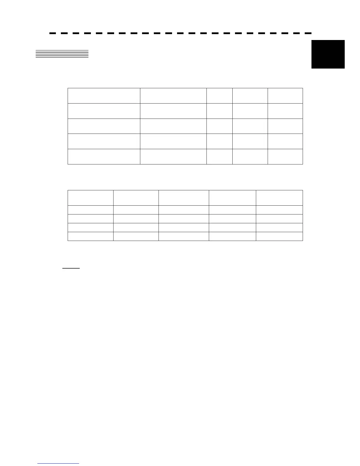
Scanners and Transmitted Output Powers
SCANNER TYPE
TRANSMITTED
OUTPUT POWER
BAND
RATE OF
ROTATION
CATEGORY
JMA-5212-4
4 FT SLOT
ANTENNA
10 KW X 27rpm CAT 3
JMA-5212-6
6 FT SLOT
ANTENNA
10 KW X 27rpm CAT 3
JMA-5222-7
7 FT SLOT
ANTENNA
25 KW X 24rpm CAT 3
JMA-5222-9
9 FT SLOT
ANTENNA
25 KW X 24rpm CAT 3
Radar Configuration and Ship’s Mains
RADAR
MODEL
SCANNER
UNIT
PERFORMANCE
MONITOR UNIT
DISPLAY UNIT SHIP’S MAINS
JMA-5212-4 NKE-2103-4 NJU-85 NCD-4380 24 VDC
JMA-5212-6 NKE-2103-6 NJU-85 NCD-4380 24 VDC
JMA-5222-7 NKE-2254-7 NJU-85 NCD-4380 24 VDC
JMA-5222-9 NKE-2254-9 NJU-85 NCD-4380 24 VDC
Notes:
1. An optional rectifier NBA-5111 is necessary for using Ship's Mains 100/110/115/200/220/230 VAC.
2. The display system NCD-4380 has a separate structure consisting of the following:
Monitor unit NWZ-164
Processor unit NDC-1460
Keyboard unit NCE-7699A
3. The ship with radar of IMO conformity must mount a PM unit.
 Loading...


