8.4 REPLACEMENT OF MAJOR PARTS
828
8
yyyy
yyyy
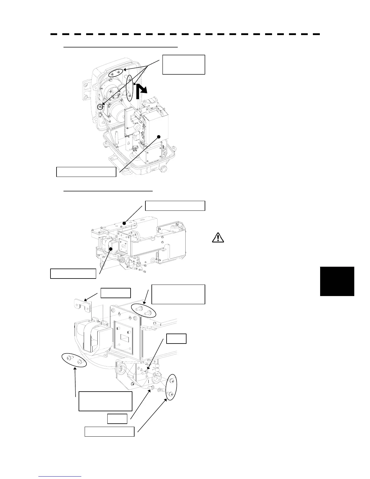
Step 4: Remove the transmitter-receiver.
Loosen all the hexagon bolts.
Slide upward and remove the
transmitter-receiver.
Step 5: Replace the magnetron.
Remove the screws (2 places) and remove the
magnetron cable.
Use a shielded screw driver.
Metal (tools) may deteriorate if they
come in contact with the magnetron.
Remove the screws (4 places) and remove the
magnetron.
Set the new magnetron in place.
Fix the magnetron and pulse transformer
cables (yellow and green, respectively)
carefully in place.
Reverse the order to complete the procedure.
Make sure that all bolts and screws are
tightened again, and all cables are properly
re-connected.
This completes the magnetron replacement
procedure.
Transmitter-receiver
Hexagon bolts
(5 places)
Transmitter-receiver
Magnetron
Screws
(2 on the back side)
Nut plate
Screws
(2 on the front side)
Green
Yellow
Screws (2 places)

 Loading...


