1-6
1-6. Checking assembly position
Once the system becomes ready for powering ON, confirm that the picking pad of shuttle and the
picking pad of X head are positioned on the same axis.
Boot the system in test mode, and after initialization, confirmation can be made by means of “H.P
Offset” of “19.XYZ ADJ” (see Section 10-19).
If the picking pad is displaced, adjustment is required.
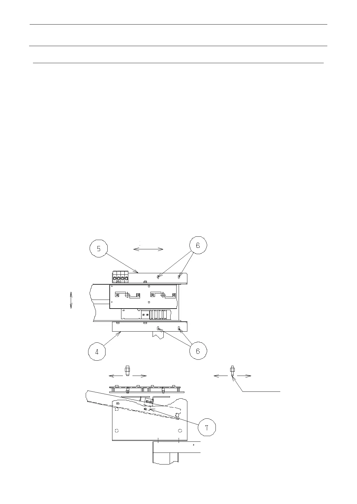
< Displacement in Y-direction >
Loosen the mounting screws of S joint base A and S joint base B , and adjust the position.
< Displacement in X-direction >
Use “H.P Offset” in “19. XYZ ADJ” of test mode for adjustment.
Move X head with the arrow key, lower the head with the HEAD key, and make confirmation.
If the value of “H.P Offset” has been changed, then change the value of “Tray Ref” as well.
If displacement has been made in the a-direction using “H.P Offset”, displace “Tray Ref” in
a’-direction by the same degree.
If displacement has been made in b-direction using “H.P Offset”, displace “Tray Ref” in
b’-direction by the same degree.
If adjustment cannot be made by means of “H.P Offset”, use S dog PL for adjustment because
the stop position of shuttle can be changed if S dog PL is moved.