3. Aach the front-mounng brackets (either the ush or the 2-in.-recess front-mounng brackets) to
the side mounng-rails by using the 6 4-40 at-head Phillips mounng screws. See Figure 71 on
page 128.
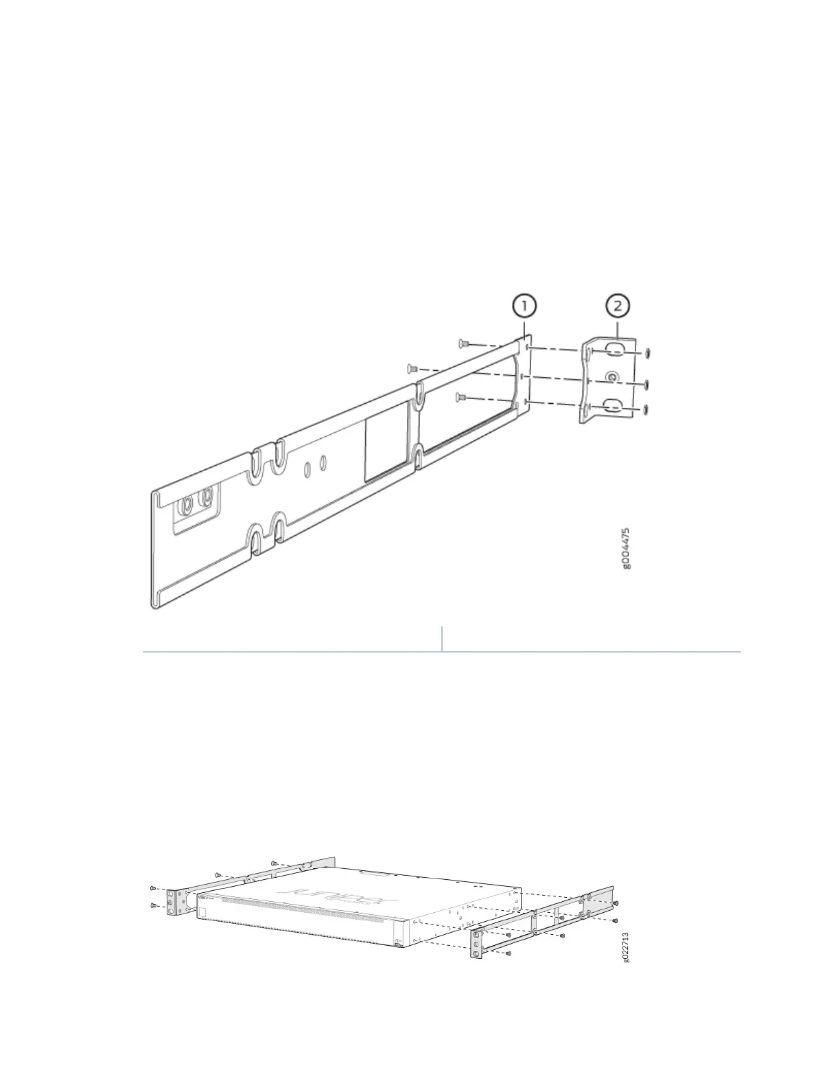
Figure 71: Aaching the Front-Mounng Bracket to the Side Mounng-Rail
1— Side mounng rail 2— Front-mounng bracket
4. Align the side mounng rails along the side panels of the switch chassis. Align the two holes in the
rear of the side mounng rails with the two holes on the rear of the side panel.
5. As shown in Figure 72 on page 128, align the side mounng rails along the side panels of the switch
chassis and insert and ghten the twelve 4x6 mm Phillips at-head mounng screws to secure the
side panels to the two sides of the switch chassis.
Figure 72: Aaching the Side Mounng Rail to the Switch Chassis
128