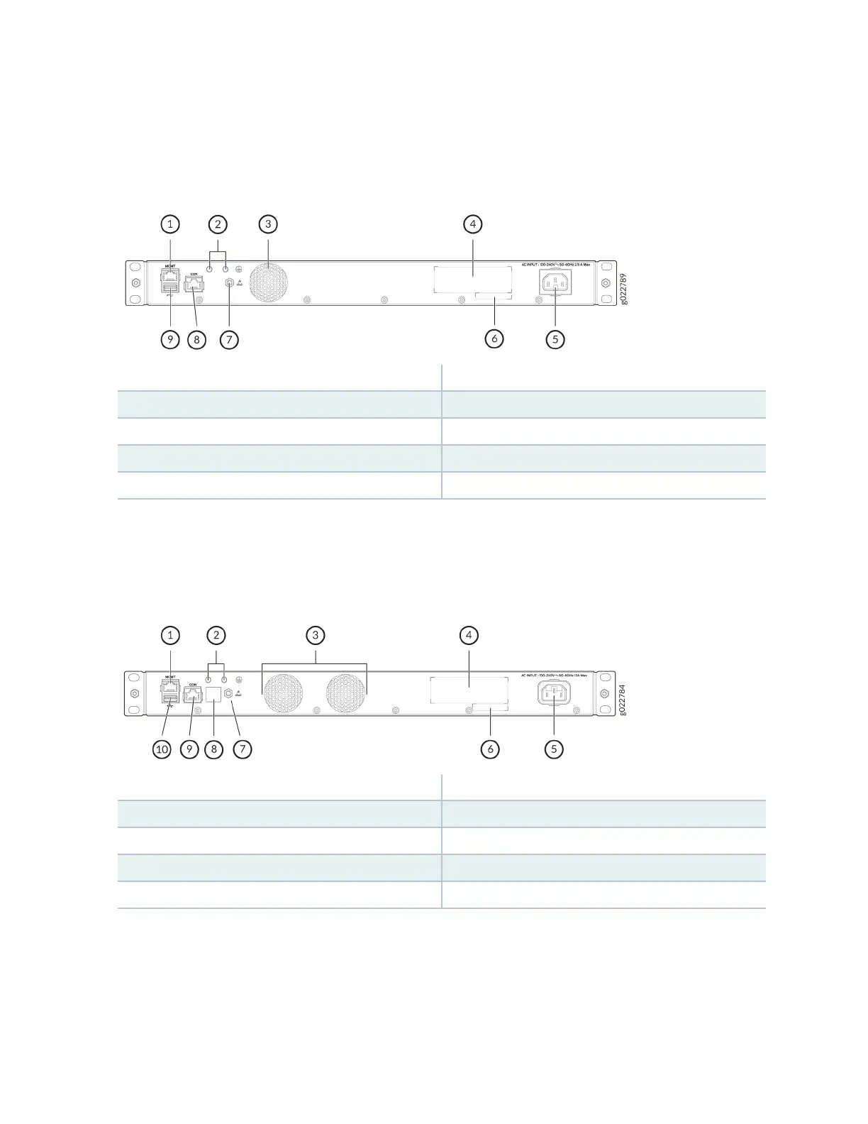
Figure 33 on page 18 shows the components on the rear panel of EX4100-F-24T switch.
Figure 33: Components on the Rear Panel of EX4100-F-24T Switch
1—
RJ-45 management port (labeled MGMT)
6—
CLEI code label
2—
Protecve earthing terminal
7—
Electrostac discharge (ESD) point
3—
Built-in fan module
8—
RJ-45 console port (labeled CON)
4—
Serial number
9—
USB 2.0 Type A port
5—
AC power supply socket
Figure 34 on page 18 shows the components on the rear panel of EX4100-F-48P switch.
Figure 34: Components on the Rear Panel of EX4100-F-48P Switch
1—
RJ-45 management port (labeled MGMT)
6—
CLEI code label
2—
Protecve earthing terminal
7—
Electrostac discharge (ESD) point
3—
Built-in fan modules
8—
Claim Code label
4—
Serial number
9—
RJ-45 console port (labeled CON)
5—
AC power supply socket
10—
USB 2.0 Type A port
18