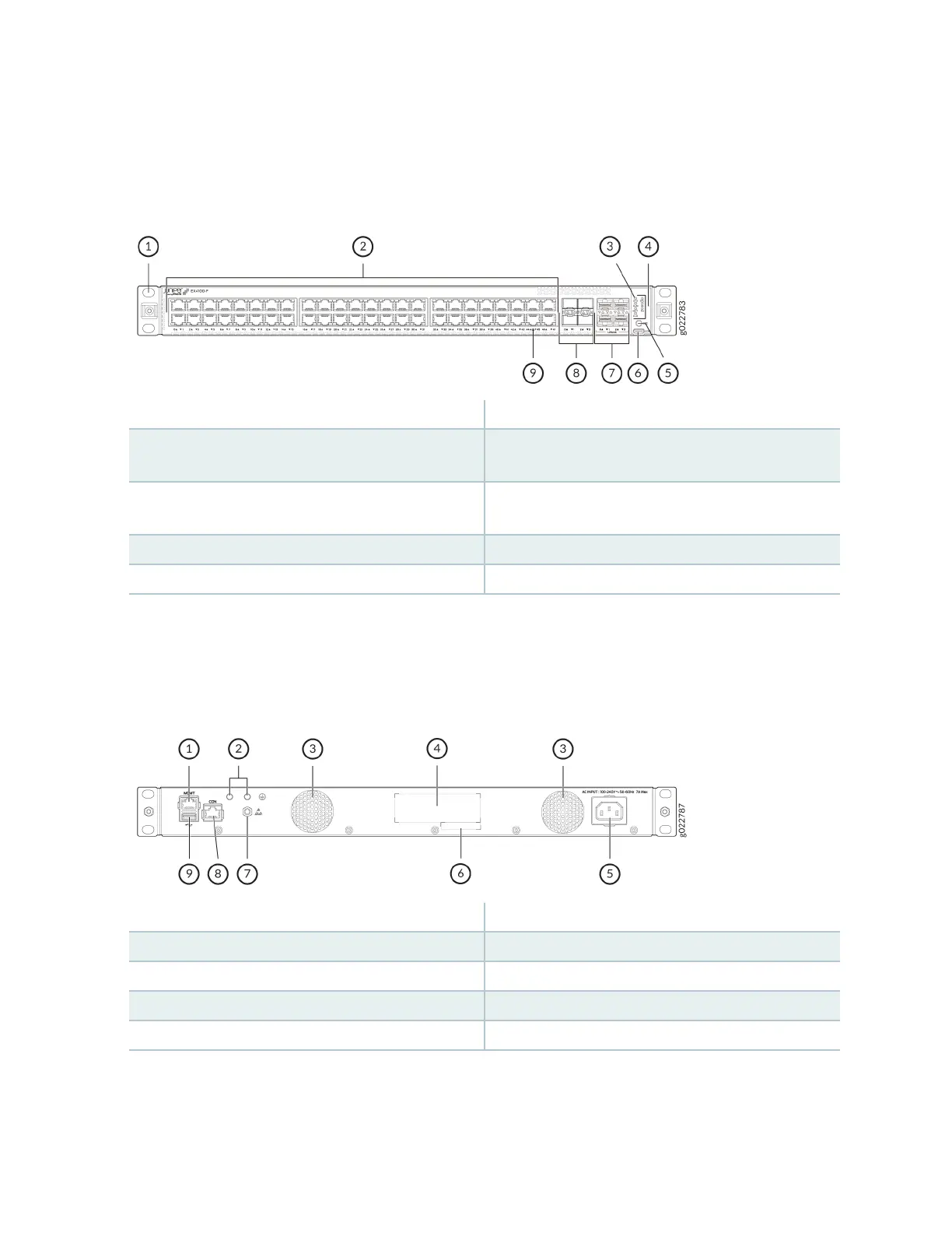
Figure 31 on page 17 shows the components on the front panel of the EX4100-F-48T switch.
Figure 31: Components on the the Front Panel of the EX4100-F-48T Switch
1—
Front mounng brackets
6—
RS232 to USB Type-C console port
2—
10/100/1000BASE-T RJ-45 non-PoE
network ports.
7—
10 GE SFP+ Uplink ports
3—
Chassis status LEDs (labeled SYS, ALM, MST,
and CLD)
8—
1/10 GE SFP+ Virtual Chassis ports
4—
Port mode LEDs (labeled SPD, DX, and EN)
9—
Reset buon
5—
Factory Reset/Mode buon
Figure 32 on page 17 shows the components on the rear panel of EX4100-F-24P switch.
Figure 32: Components on the Rear Panel of EX4100-F-24P Switch
1—
RJ-45 management port (labeled MGMT)
6—
CLEI code label
2—
Protecve earthing terminal
7—
Electrostac discharge (ESD) point
3—
Built-in fan modules
8—
RJ-45 console port (labeled CON)
4—
Serial number
9—
USB 2.0 Type A port
5—
AC power supply socket
17