• A chassis cluster IP monitoring failure.
• O–The node is not congured for clustering or it has been disabled by the dual
membership and detecon recovery process in reacon to a control link or fabric link
failure.
LINK/ACT LED, one for each of the two ports CHASSIS CLUSTER CONTROL 0 and CHASSIS
CLUSTER CONTROL 1:
• Green–Chassis cluster control port link is acve.
• O–No link.
ENABLE LED, one for each of the two ports CHASSIS CLUSTER CONTROL 0 and CHASSIS
CLUSTER CONTROL 1:
• Green–The chassis cluster control port is enabled.
• O–The chassis cluster control port is disabled.
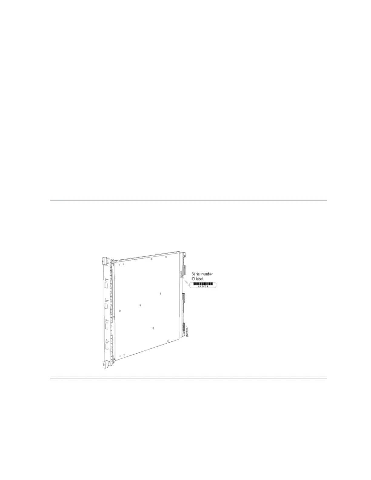
Serial Number
Locaon
The serial number label is located as shown in Figure 5 on page 19.
Figure 5: Serial Number Label (IOC Shown, Other Cards Similar)
Services Processing Card SRX5K-SPC3 Specicaons
The SRX5K-SPC3 Services Processing Card (SPC) contains two Services Processing Units (SPUs) with
128GB of memory per SPU, that provide the processing power to run integrated services such as
rewall, IPsec, and IDP (see Figure 6 on page 20). All trac traversing the rewall is passed to an SPU
19

 Loading...


