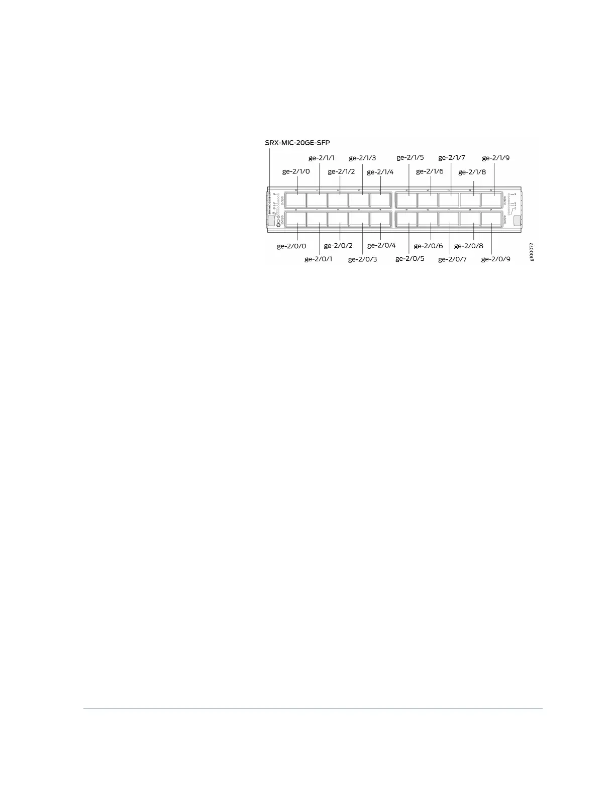
Figure 21: SRX-MIC-20GE-SFP Interface Port Mapping
The SRX-MIC-20GE-SFP MIC contains two logical PICs, numbered
PIC 0 through PIC 1 in the CLI. Each logical PIC contains 10 ports
numbered 0 through 9.
The sample output of the show chassis fpc pic-status command
output displays two 20-port Gigabit Ethernet MICs with SFP —
inserted into the slots of an MPC in slot 2.
The logical PICs of the two MICs— 10x 1GE(LAN) SFP — are shown as
PIC 0, PIC 1, PIC 2, and PIC 3.
user@host> show chassis hardware
node1:
--------------------------------------------------------------------
------
Slot 1 Online SRX5k SPC II
PIC 0 Online SPU Cp
PIC 1 Online SPU Flow
PIC 2 Online SPU Flow
PIC 3 Online SPU Flow
Slot 2 Online SRX5k IOC II
PIC 0 Online 10x 1GE(LAN) SFP
PIC 1 Online 10x 1GE(LAN) SFP
PIC 2 Online 10x 1GE(LAN) SFP
PIC 3 Online 10x 1GE(LAN) SFP
{primary:node1}
The show interfaces terse command output displays the Gigabit
Ethernet interfaces that correspond to all the ports located on the
two MICs.
48

 Loading...


