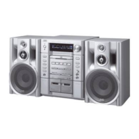
MX-J170V
1-10
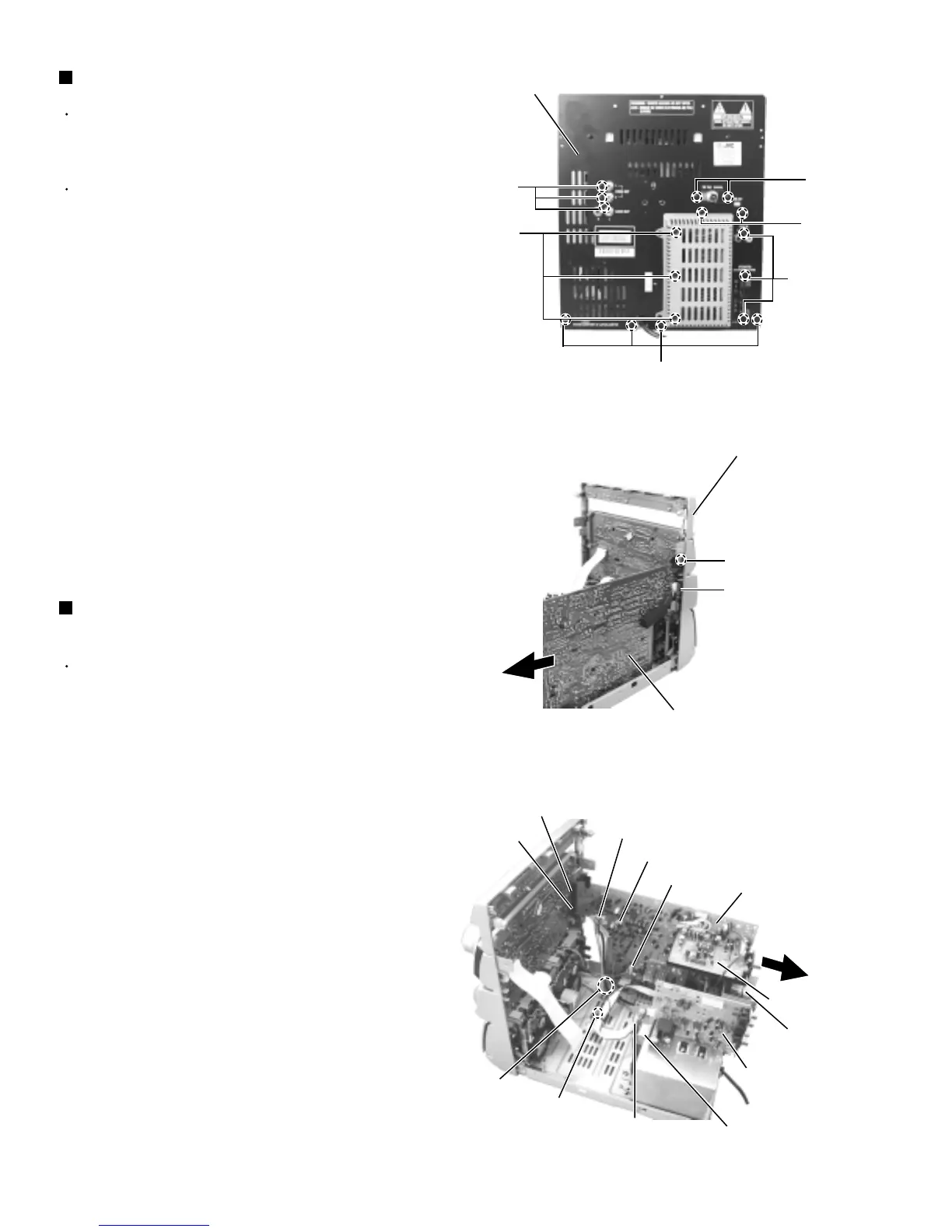
Prior to performing the following procedure, remove
the top cover, the side covers, the CD Tray fitting
and the CD changer unit.
There is no need to remove the front panel
assembly.
Remove the ten screws G attaching the main board,
the tuner board and the heat sink to the rear panel
on the back of the body.
Remove the three screws H attaching the VCD
power board to the rear panel on the back of the
body.
Remove the four screws I attaching the rear panel on
the back of the body.
1.
2.
3.
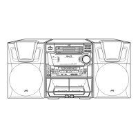
Removing the rear panel (See Fig.17)
Prior to performing the following procedure, remove
the rear panel.
Disconnect the harness from connector HCW1 of the
MIC/headphone board on the right side of the body.
Release the harness from the clamp in the body.
Disconnect the harness from head wire connector
ECW1,DW1 and DW2 extending to the main board
in the body.
Disconnect the harness from connector RCW1 of the
power transformer.
Remove the screws D attaching the front panel
assembly on both sides of the body.
Remove the screw J attaching the earth terminal to
the base chassis.
Disconnect connector CCW1 and CCW2 connected
to the main board.
1.
2.
3.
4.
5.
6.
Removing the main board
(See Fig.18 and 19)
Fig.17
Fig.18
Fig.19
G
Rear panel
G
G
I
H
Front panel assembly
Main board
MIC/
headphone board
HCW1
Main board
Heat sink
Tuner board
DW2
DW1
CCW2
CCW1
Power transformer
RCW1
J
Clamp
G
ECW1
D
VCD board