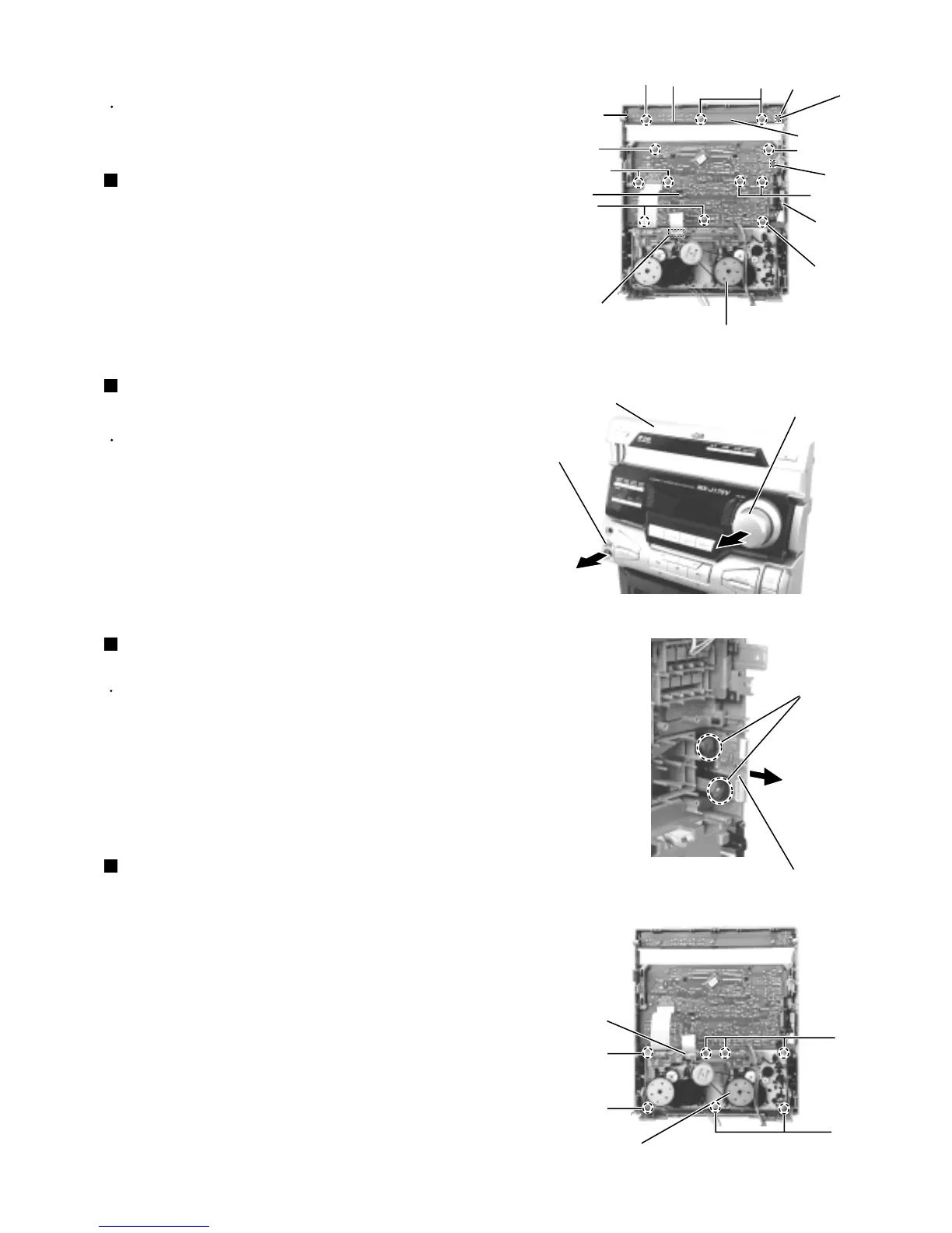
Prior to performing the following procedure, remove
the power / CD switch board.
Pull out the volume knob toward the front.
Disconnect the card wire from the mechanism board
of the cassette mechanism assembly.
Remove the nine screws T attaching the front board.
1.
2.
3.
Removing the front board
(See Fig.27 and 28)
Remove the three screws S attaching the power/CD
switch board and release the three tabs h outward.
Disconnect the harness from connector UCW9 of
the power / CD switch board.
1.
2.
Prior to performing the following procedure, remove
the top cover, the side covers, the CD tray fitting and
the front panel assembly.
Removing the power / CD switch board
(See Fig.27)
Disconnect the card wire from the mechanism board
of the cassette mechanism assembly.
Remove the seven screws V attaching the cassette
mechanism assembly.
1.
2.
Removing the cassette mechanism
assembly (See Fig.30)
<Front panel assembly>
Pull out the MIC level knob toward you.
Remove the two screws U attaching the
MIC/headphone board.
1.
2.
Removing the MIC/headphone board
(See Fig.28 and 29)
Prior to performing the following procedure, remove
the front board.
Fig.27
Fig.28
Fig.29
Fig.30
Tab h
Power / CD
switch board
S
T
MIC/
headphone
board
Tab h
Tab h
Cassette mechanism assembly
JW1
S
T
T
T
T
T
Front board
Mechanism board
Front panel assembly
Volume knob
MIC/headphone board
U
Cassette mechanism assembly
Mechanism board
V
V
V
V
UCW9
MIC level knob