Connection Settings
m
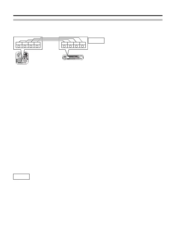
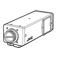
Control Signal Cable Connection on Camera (Rear)
Memo
Connect the cables correctly such
that the A,B, C, D marks of the
camera terminals coincide with those
of the RM-P2580 terminals.
m
Rear Switch Settings (A page 26)
Set the [RX TERM OFFlON] switch.
Set only the camera connected by the control signal line to “ON”. Set to
“OFF” for all other cameras.
m
Menu Screen Settings (A page 34)
① Select the [MAINTENANCE] item on the [MENU] screen, and
press the [SET] button.
The [MAINTENANCE] screen appears.
② Move the cross key up/down to select the [COMMUNICATION]
item, move the cross key to the left/right to set to “JCCP”,
followed by pressing the [SET] button.
The [COMMUNICATION (JCCP)] screen appears.
③ Set [PROTOCOL 1] to “MULTIDROP”.
④ Set [PROTOCOL 2] to “DUPLEX”.
⑤ Set the [MACHINE ID] item according to the number of the
RM-P2580[VIDEO INPUT] terminal on each camera.
⑥ Press the [MENU] button to exit setting.
⑦ Turn off and on the power.
Memo
v
Turn off the power of the device to be used.
v
Refer also to the instruction manual of the device to be
used.
v
For details on the type of connection cable and distance,
refer to "Power Supply Connection" (A page 22).
v
Control signal cables do not support loop connection.
CAMERA
1
TO CAMERA DATA I / O
RX
+
RX
-
TX
+
TX
-
COM
1 2 3 4 5 6 7 8
COM
9/110/2 11/312/413/514/615/716/8
COMCOM COM
CAMERA
SW
UNIT
ALARM
AUTO
4312 8756
2 3 4 5 6 7
8
1
MONITOR
OUTPUT
MONITOR
SERIAL-2SERIAL-1
VIDEO INPUT
VIDEO OUTPUT
OUTPUT
2
1
ON
2 3 4 5 6 7
8
RM-P2580
RX
-
RX+
TX
-
TX+
A
B C D
RX
-
RX+
TX
-
TX+
A
B C D
Connection/Installation
E-19