Mounting and installation User Manual B-Net 93 60
20 © Kaba Benzing GmbH 01/2006
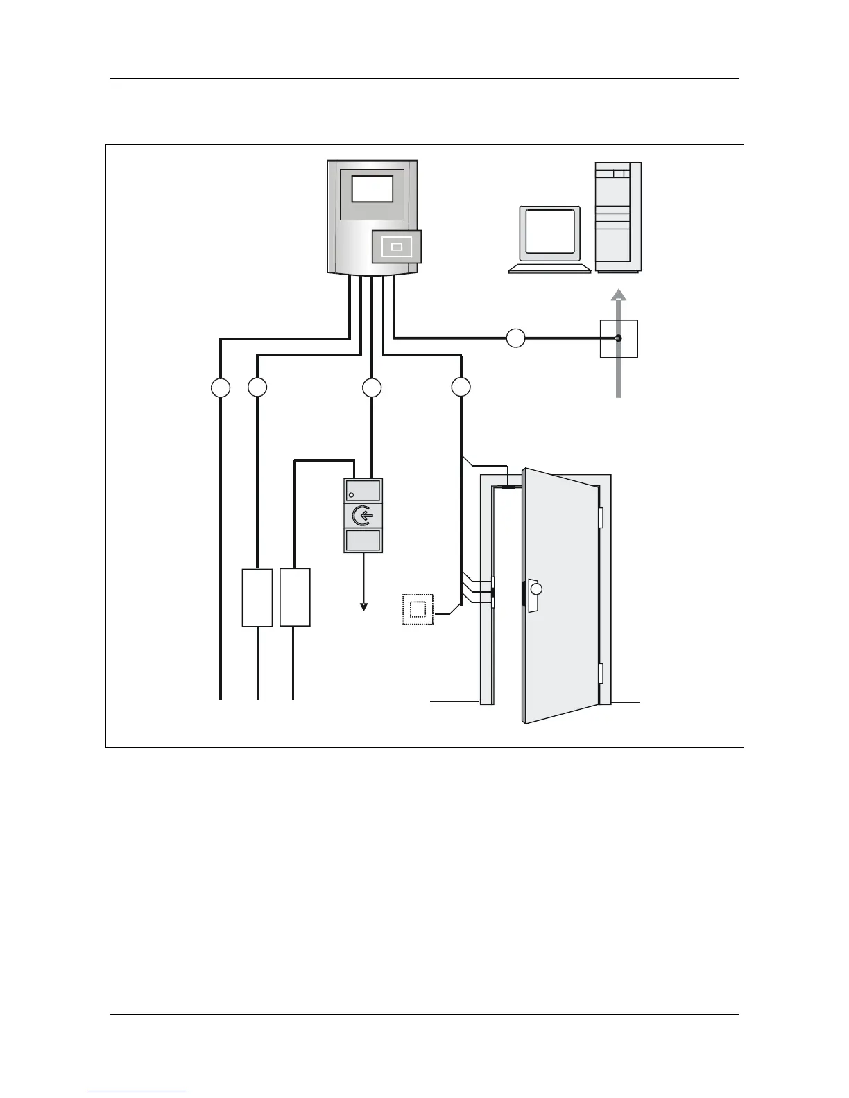
5.2 Installation scheme
5
3
1
2
115 V / 230 V AC
4
7
8
9
10
11
12
13
6
Fig. 8: B-Net 93 60 installation scheme
1 Power supply internal* 8 Subterminal
2 Power supply external* 9 External power supply e.g. SV905
3 Data line subterminal 10 Door-opener push button
4 Door control 11 Door-frame contact
5 Host connection 12 Door handle contact, door opener, and bolt
contact
6 B-Net 93 60 13 Door opener door 2
7 Host computer
* alternatively
 Loading...