Fig. 1 Maximum relative humidity of intake air ..................................................................................... 6
Fig. 2 Location of safety signs .............................................................................................................. 23
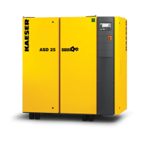
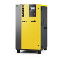
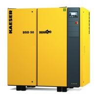
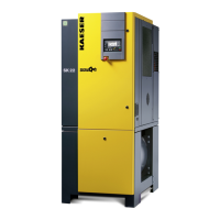
Fig. 3 Enclosure overview .................................................................................................................... 26
Fig. 4 Machine layout ........................................................................................................................... 27
Fig. 5 Keys – overview ......................................................................................................................... 28
Fig. 6 Indicators – overview .................................................................................................................. 29
Fig. 7 RFID reader ................................................................................................................................ 30
Fig. 8 Machine mountings .................................................................................................................... 33
Fig. 9 Recommended machine placement and dimensions [mm] ........................................................ 36
Fig. 10 Compressed air pipework ........................................................................................................... 39
Fig. 11 Charging hole ............................................................................................................................. 44
Fig. 12 Activating and deactivating the MODULATING control .............................................................. 45
Fig. 13 Position of the door interlock switch ........................................................................................... 47
Fig. 14 Switching on and off ................................................................................................................... 48
Fig. 15 Switching off in an emergency ................................................................................................... 49
Fig. 16 Using the remote control for switching on and off ...................................................................... 50
Fig. 17 Using the timer for switching on and off ..................................................................................... 51
Fig. 18 Acknowledging messages .......................................................................................................... 52
Fig. 19 Filter mat for the air and oil cooler .............................................................................................. 59
Fig. 20 Switching cabinet ventilation ...................................................................................................... 60
Fig. 21 Filter mat for the air and oil cooler .............................................................................................. 61
Fig. 22 Air filter maintenance .................................................................................................................. 62
Fig. 23 Drive belt maintenance ............................................................................................................... 63
Fig. 24 Check the EMERGENCY STOP control device ......................................................................... 65
Fig. 25 Checking the cooling oil level ..................................................................................................... 66
Fig. 26 Venting the machine ................................................................................................................... 67
Fig. 27 Replenish cooling oil .................................................................................................................. 68
Fig. 28 Changing the cooling oil, oil separator tank ............................................................................... 71
Fig. 29 Changing the cooling oil Oil cooler ............................................................................................. 72
Fig. 30 Changing the cooling oil, heat recovery system ......................................................................... 73
Fig. 31 Changing the oil filter .................................................................................................................. 74
Fig. 32 Changing the oil separator cartridge .......................................................................................... 76
Fig. 33 Transporting with a forklift truck ................................................................................................. 86
Fig. 34 Transporting with a crane ........................................................................................................... 87
Fig. 35 Battery labelling .......................................................................................................................... 88
List of Illustrations
901848 21 E
Operating Manual Rotary screw compressor
SK
v
 Loading...