GB - 14
KEB COMBICONTROL
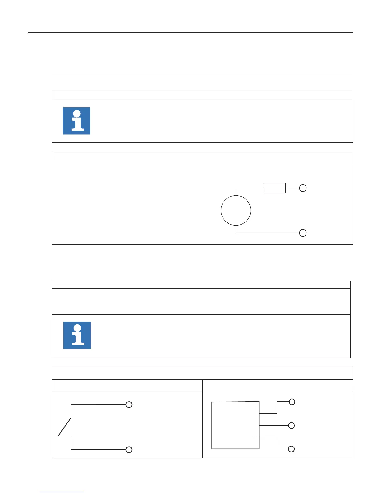
2.3.3 Voltage supply for the inputs and outputs
The voltage for supply of the digital inputs and outputs (UM) occurs via the terminals X2.1 to
X2.8 in accordance with picture 2.3.3 and is electrically insulated from US.
%IB1
Is set in case of overload at one or several outputs. Additionally the OL-LED
(red) is set.
%IB2 Condition of the supply voltage in/outputs (UM)
Address can be changed in the unit editor.
Picture 2.3.3 Voltage supply for the inputs and outputs
U = 18…30 V DC ±0 %
F2 = 6.3 A type gG
+
-
U
F2
X2.1...4
X2.5...8
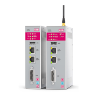
2.3.4 Digital inputs (X2.11…14)
The digital inputs are potential-free to the control voltage US.
4 digital outputs 0...3
%IB0 Condition of the digital inputs 0…3.
Address can be changed in the unit editor.
Picture 2.3.4 Connection of the digital inputs
Potential-free connection Connection e.g. via PLC
X 2.2 (+UM)
X 2.12 (I1)
+
-
X2.2 (+UM)
X2.5 (- UM)
X2.12 ( I1 )
П