9
2
19
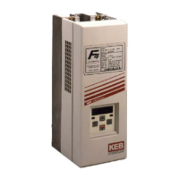
KEB COMBIVERT F5
Name: Basis
10.04.02
2
© KEB Antriebstechnik, 2002
All Rights reserved
Product Description Summary
Section PageDate Chapter
Inverter Size 20 21 22 23 24
Housing size RRRRRRUUU
Phases 33333
Output nominal power [kVA] 52 62 80 104 125
Max. rated motor power [kW]3745557590
Output nominal current [A] 75 90 115 150 180
Max. short time current
1)
[A] 112 135 172 225 270
OC-tripping current [A] 135 162 207 270 324
Nominal input current [A] 83 100 127 165 198
Max. permissible mains fuse (inert) [A] 100 160 160 200 315
Rated operating frequency [kHz] 848482848
Max. operating frequency [kHz] 16 16 16 16 16 12 8 8 8
Power loss at nominal operating [W] 900 1000 1100 1200 1500 1300 1900 2000 2400
Stall current at 4kHz
2)
[A] 75 90 115 – 150 180
Stall current at 8kHz
2)
[A]75639080115–150117180
Stall current at 16kHz
2)
[A]3445544651––––
Max. heat sink temperature TOH [°C] 90
Motor line cross section
3)
[mm²]3550509595
Min. braking resistor
4)
[Ohm] 9 9 9 6 5 4
Typ. braking resistor
4)
[Ohm]1311966
Max. braking current [A] 88 88 88 133 160 200
Overload curve 1
Tightening torque for terminals [Nm] 6 15
Mains voltage
5)
[V] 305...500 ±0 (400 V Nominal voltage)
Mains frequency [Hz] 50 / 60 +/- 2
Output voltage [V] 3 x 0...U Mains
Output frequency [Hz] see Control board
Max. shielded motor line length [m] 50
Storage temperature [°C] -25...70 °C
Operating temperature [°C] -10...45 °C
Model / protective system IP20
Relative humidity max. 95% without condensation
EMC tested according to product standard EN 61800-3
Climatic category 3K3 in accordance with EN 50178
1) With the regulated systems F5-M as well as F5-S 5% are to be subtracted as control reserve.
2) Max. current before the responding of the OL2-function (only F5-M; F5-S; F5-A)
3) Recommended minimum cross section for rated power and a cable length of upto 100m (copper)
4) This data is only valid for units with internal brake transistor GTR 7 (see "unit identification")
5) At mains voltage ≥ 460V multiply the nominal current with factor 0,86.
 Loading...


