5
6
35
KEB COMBIVERT F5
Name: Basis
28.01.03
6
Section PageDate
© KEB Antriebstechnik, 2002
All rights reserved
Chapter
Functional DescriptionDigital In- and Outputs
6.3.5 Digital Filter (di.3)
The digital filter reduces the susceptibility to interferences on the digital inputs. With
di.3 a response time is adjusted. For the duration of the adjusted time the conditions
of all inputs must remain constant, so that a transfer occurs. The transfer takes place
at the positive edge of the scanning grid (see Fig. 6.3.7).
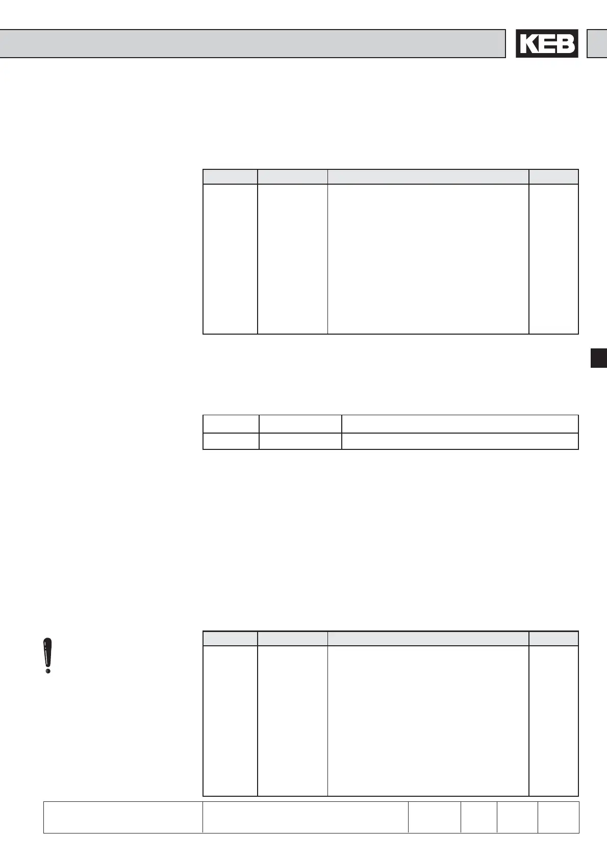
Parameter Setting range Response time
di.3 0...127 (adjusted value +1) x program run time
Program run time: 1 ms at F5-General; 2 ms at F5-Basic
6.3.6 Inversion of In-
puts (di.4)
With parameter di.4 it can be adjusted, whether a signal is 1- or 0-active (inverted).
The parameter is bit-coded, i.e. according to the table below, the appropriate value for
the input is to be entered. If several inputs shall be inverted, then the sum is to be
formed. (Exception: An inversion of the control release remains without function).
6.3.7 Edge-triggering
(di.5)
As a standard the inverter is controlled with static signals, i.e. an input is set for as
long as a signal is applied. However, practice has shown that a signal may be available
for a limited time only, but the input shall still remain set. In that case the input or
several inputs can be adjusted to edge-triggering. Then a rising edge with a pulse
duration that is longer than the response time of the digital filter is sufficient for switch-
on. Switch-off is effected with the next rising edge.
Control release (ST) can be
set to edge-triggering, but
remains without affect on the
function, since it is a pure
static signal.
6.3.4 Terminal Status
(ru.21)
The terminal status shows the logic level on the input terminals. It is unimportant,
whether the inputs are internally active or not. If a terminal is controlled, then the
appropriate decimal value according to the table below is output. If several terminals
are active, then the sum of the decimal values is output.
Example: ST, F and IB are controlled ➭ indicated value = 1+4+512 = 517
Bit -No. Decimal value Input Terminal
0 1 ST (Prog. input „Control release/Reset“) X2A.16
1 2 RST (Prog. input „Reset“) X2A.17
2 4 F (Prog. input „Forward“) X2A.14
3 8 R (Prog. input „Reverse“) X2A.15
4 16 I1 (Prog. input 1) X2A.10
5 32 I2 (Prog. input 2) X2A.11
6 64 I3 (Prog. input 3) X2A.12
7 128 I4 (Prog. input 4) X2A.13
8 256 IA (Internal input A) none
9 512 IB (Internal input B) none
10 1024 IC (Internal input C) none
11 2048 ID (Internal input D) none

 Loading...


