6 12
KEB COMBIVERT F5
6
Name: Basis
04.05.04
Chapter Section Page Date
© KEB Antriebstechnik, 2002
All rights reserved
Functional Description Technology Control
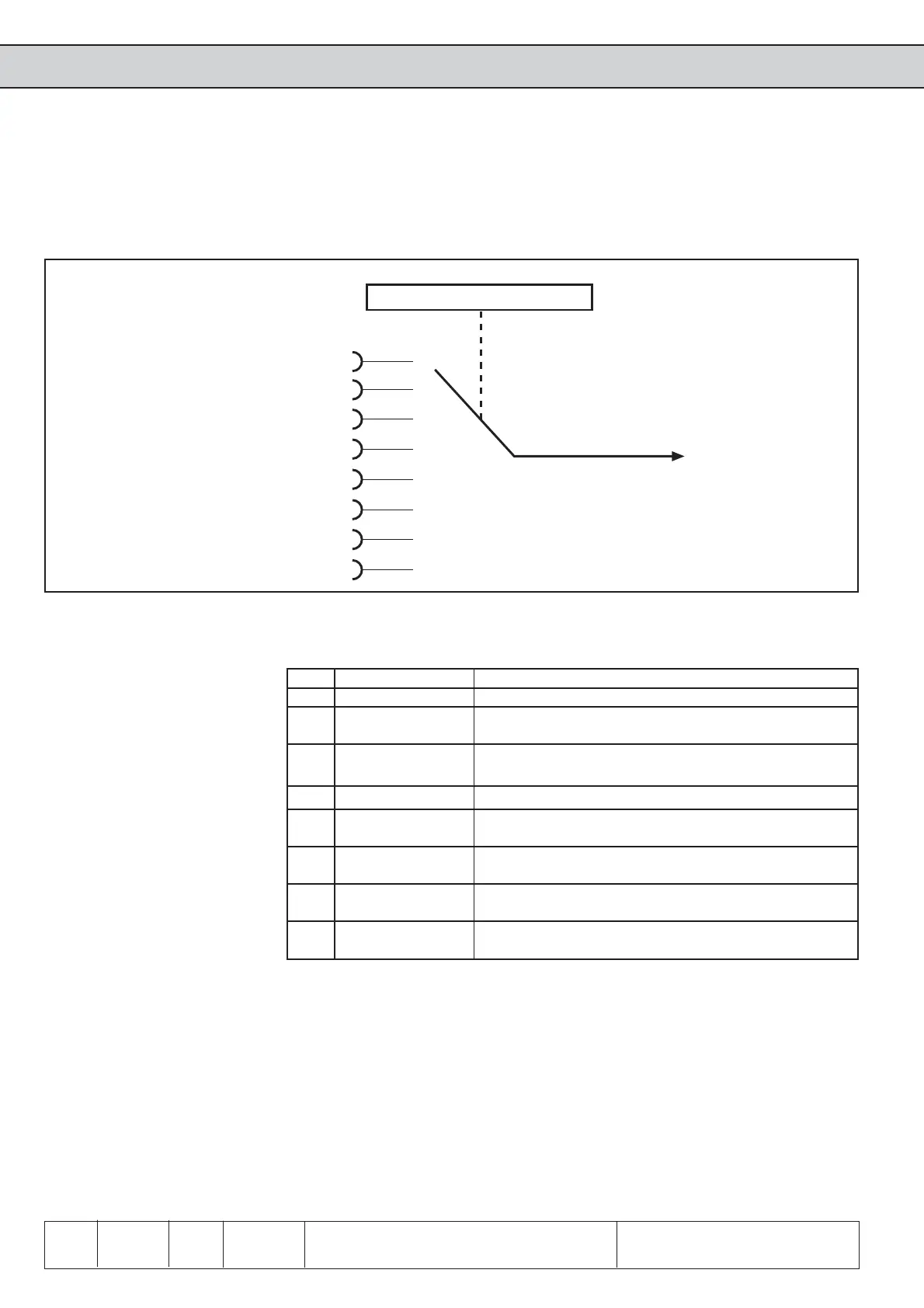
Pic. 6.12.3 PID controller actual value
6.12.3 PID Actual Value
This section describes the PID-controller actual value. The actual value input is adjusted
with the PID-reference source (cn.2).
PID actual value source (cn.2)
The actual value source (cn.2) determines from where the PID-Controller receives the
actual value signal. Following signals are available:
cn.2 Signal Function
0 AN1 Signal of the analog input 1 (see chapter 6.2)
1 AN2 Signal of the analog input 2 (see chapter 6.2)
- reserved at B control -
2 AN3 Signal of the analog input 3 (see chapter 6.2)
- reserved at B control -
3 Aux Signal of the Aux input (see chapter 6.2)
4 cn.3 PID absolute actual value is preset with cn.3 in the
range of -400,0...400,0 %
5 Active current The active current -200…200 % displayed in parameter
ru.17 is used as actual value signal (100 % = I
rated
)
6 Utilization The utilization 0…255 % displayed in parameter ru.13
is used as actual value signal (100 % = 100 %)
7 DC-voltage The DC-voltage 0...1000 V displayed in parameter
ru.18 is used as actual value signal (100 % = 1000 V)
0
1
2
3
4
5
6
7
cn.2 PID actual value source
Analog input An1 (ru.28)
Analog input An2 (ru.30)
Analog input An3 (ru.32)
Aux input (ru.53)
PID controller
Active current (ru.17)
Utilization (ru.13)
DC-voltage (ru.18)
PID absolute actual value (cn.3)

 Loading...


