6 7
KEB COMBIVERT F5
6
Name: Basis
04.05.04
Chapter Section Page Date
© KEB Antriebstechnik, 2002
All rights reserved
Functional Description Protective Functions
Param. Adr.
min
max
default
ENTER
PROG.
R/W
Step
Pn.19 0413h ✔✔✔ 0 255 1 0 bit-coded
Pn.20 0414h ✔✔- 0 % 199 % (200 = oFF) 1 % oFF % referring to inverter rated current
Pn.21 0415h ✔✔- 0.00 s 300.00 s 0.01s 2.00 s -
Used Parameters
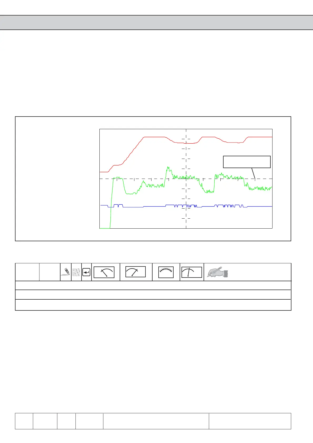
Fig. 6.7.2 Functioning of Stall-function with standard setting
Actual frequency (ru.3)
Inverter status (ru.0)
Actual utilization (ru.13)
adjusted constant
current limit
Pn.20 Stall level
The max. constant current represents the setpoint for the control. The adjusted value
refers to the inverter rated current (In.1).
Setting range: 0...199 %; 200 = off (default)
Depending on the setting of Pn.19 (bit 3) the ramp time or the time constant of the
differential controller is adjusted here. The adjusted ramp times refer to 100 Hz /
1000 min
-1
(depending on ud.2).
Setting range: 0...300.00 s (2.00 s default)
Pn.21 Stall Acc/Dec time
 Loading...


