6
93
KEB COMBIVERT F5
Name: Basis
04.05.04
6
Section PageDate
© KEB Antriebstechnik, 2002
All rights reserved
Chapter
Functional DescriptionSpecial Functions
6.9 Special
Functions
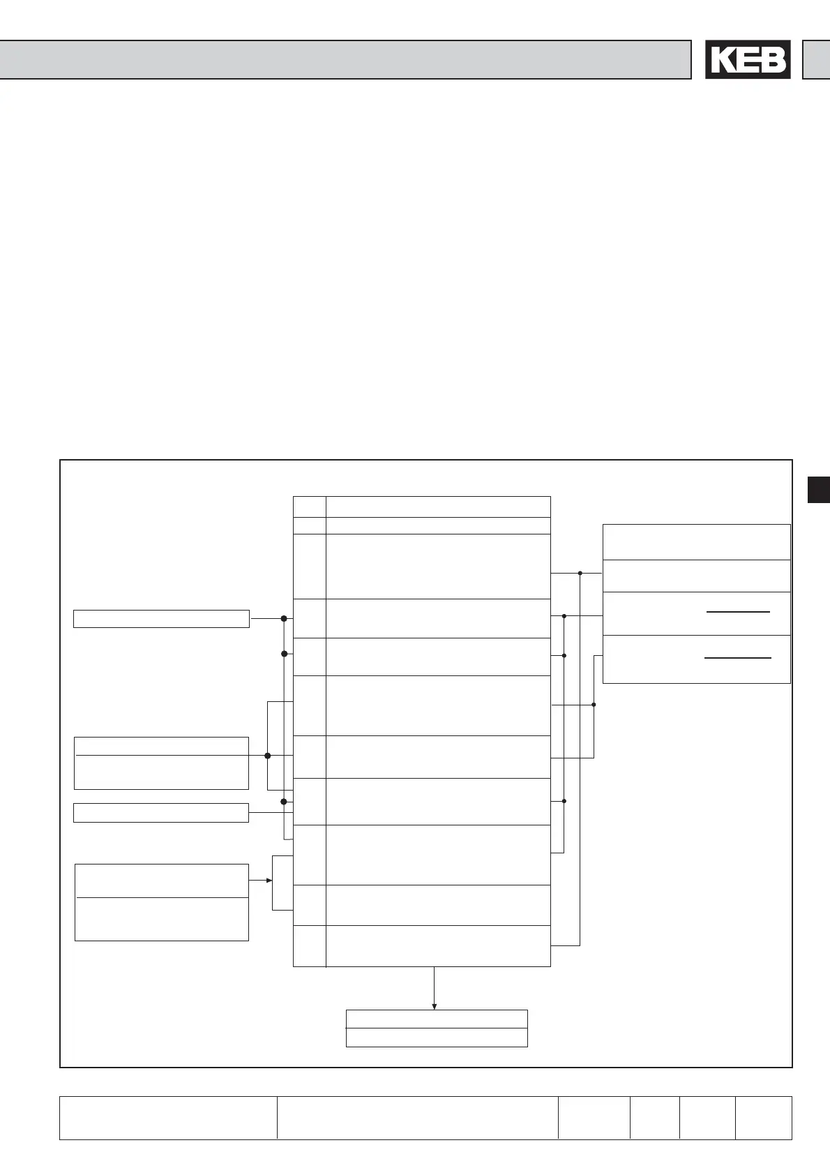
Fig. 6.9.1 Principle of DC-brake
6.9.1 DC-Braking
During the DC-braking the motor is not decelerated over the ramp. The fast deceleration
is done with DC-voltage, that is given onto the motor winding.
Between the activation and the triggering of DC-braking a time constant called Base-
Block time (bbl) of 150…5000 ms (depending on the power circuit) is necessary. It
serves as protection of the power modules during the motor de-excitation time.
With Pn.28 one adjusts through what the DC-brake is triggered. According to the
adjusted mode one can preset with Pn.32 the frequency/speed from which the DC-
brake is triggered. Pn.30 defines the braking time. The maximum braking voltage is
adjusted with Pn.31. The brake controllers are dimensioned 1:1 of inverter to motor,
thus the maximum braking voltage must be reduced in the case of deviating
dimensioning to prevent the overheating of the motor. At large ratings the maximum
braking voltage can lead to overcurrent errors (OC). In that case reduce it with Pn31.
Pn.29 is bit-coded and defines the inputs which trigger DC-braking.
The following section should facilitate the adjustment and programming of special
functions.
Pn.30 DC-brake/ time
Pn.32 DC-brake Start value
Set brake time = Pn.30
Act.brake time=
Pn.30 · factual
reference value 1)
Act.brake time=
Pn.30 · Pn.32
reference value 1)
Pn.28 DC-Braking/Activation
0 DC-braking not activated
1 DC-braking after reaching 0Hz/rpm and
missing rotation setting; max. for the
adjusted DC-braking time Pn.30 (indepen-
dent of actual frequency/spped) or until
the next setting of rotation direction.
2 DC-braking as soon as rotation direction
is missing; braking time is dependent on
actual frequency / speed
3 DC-braking as soon as rotation direction
changes; braking time is dependent on
actual frequency/speed
4 DC-braking as soon as rotation setting is
missing and the actual frequency/speed
falls below the adjusted level in Pn.32;
braking time is dependent on Pn.32
5 DC-braking as soon as the actual fre-
quency/speed falls below the adjusted
level in Pn.32; braking time is dependent
onPn.32
6 DC-braking as soon as setpoint value
ru.1 falls below the adjusted level in Pn.32;
braking time is dependent on actual
frequency/speed
7 DC-braking as soon as an input
programmed to DC-braking is active;
braking time is dependent on actual
frequency/speed; restart only after the
input is deactivated.
8 DC-braking as long as an input
programmed to DC-braking is active.
9 DC-braking after enabling the modulation
(direction of rotation + control release) for
the time adjusted in Pn.30.
Pn.31 DC-brake/max. voltage
0...25.5% (default 25,5 %)
ru.3 Actual frequency / speed
Pn.29 Input selection/
DC-braking
0...4095 (default 128)
also see 6.3
„Digital inputs“
Pn.32 DC-brake/start value
0...400 Hz (default 4Hz)
0...4000 rpm (default 120 rpm)
ru.1 Setpoint display
(only F5-B, F5-G and
F5-M if cS.0=0)
1) Reference value:
100/200/400 Hz
1000/2000/4000 rpm
depending on ud.2
 Loading...


