EasyManua.ls Logo

KEB COMBIVERT F5 Servo User Manual

KEB COMBIVERT F5 Servo
378 pages
To Next Page IconTo Next Page
To Previous Page IconTo Previous Page
Page #316 background imageLoading...
Page #316 background image
6 13
KEB COMBIVERT F5
4
Name: Basis
04.05.04
Chapter Section Page Date
© KEB Antriebstechnik, 2002
All rights reserved
Functional Description CP-Parameter Definition
6.13.2 Assignment of
CP-Parameters
ud.16 determine the parameter address (see Chapter 5) of the parameter to be displayed:
ud.16
-1: Parameter not used
0...32767: Parameter address
ud.17 determine the set, the addressing and the standardization of the parameter to be
displayed. The parameter is bit-coded. The individual bits are decoded as follows:
Bit 0...7 determines the set selection for direct set programming, i.e. all selected sets
contain the same value, which is defined by the CP-parameter. If direct set programming
(bit 8, 9) is selected at least one set must be selected as otherwise an error message is
triggered in the cp mode.
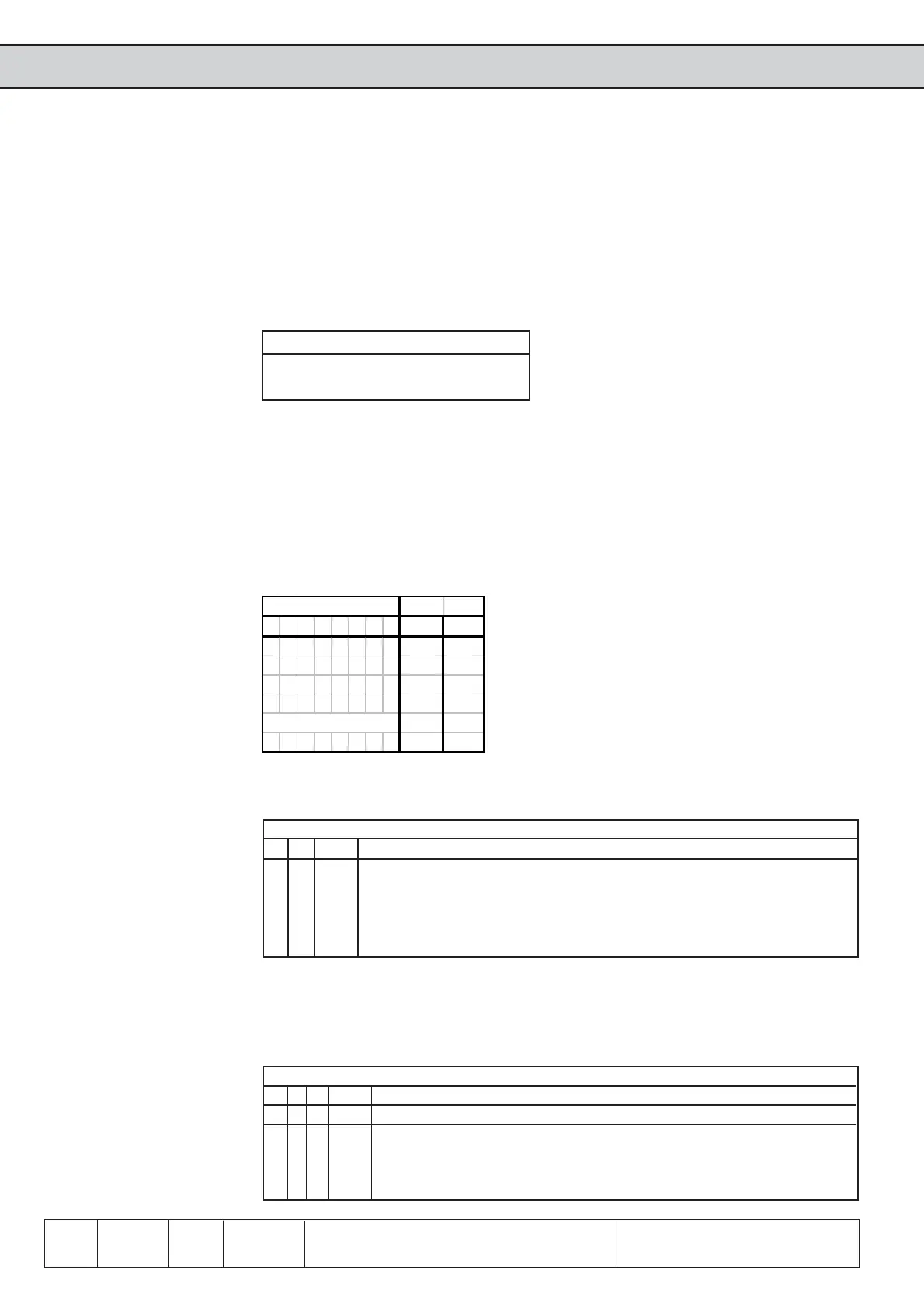
CP address (ud.16)
Determination of
parameter set for indirect
set addressing
Bit
76543210ValueSet
0 0 0 0 0 0 0 0 0 none
00000001 1 0
00000010 2 1
00000011 3 0+1
... ... ...
11111111 255 All
Determination of set
addressing mode
Bit 8 and 9 determine the set addressing mode:
Bit
8 9 Value Function
0 0 0 Direct set addressing; the sets determined by Bit 0...7 are valid
0 1 256 Current set; the current set is displayed / edited
1 0 512 Indirect set addressing, the parameter set determined with the set pointer
Fr.9 is displayed / edited
1 1 768 free
Display standardization Bit 10...12 determine how the defined parameter value is displayed. Up to seven different
user standardizations (see further on in this chapter) can be determined with the parameters
ud.18...21.
Bit
12 11 10 Value Function
0 0 0 0 Use standard standardization of the parameter
0 0 1 1024 Display standardization from set 1
0 1 0 2048 Display standardization from set 2
... ...
1 1 1 7168 Display standardization from set 7
CP set norm (ud.17)
CP selector (ud.15)
With ud.15 the CP-parameter to be programmed is adjusted in the range of 1...36. CP.0 is
not adjustable.
Invalid or not exists parameter
addresses are ignored with „Data
invalid“.
-> Data invalid, if Bit 8 and 9 = 0

Table of Contents

Other manuals for KEB COMBIVERT F5 Servo

Question and Answer IconNeed help?

Do you have a question about the KEB COMBIVERT F5 Servo and is the answer not in the manual?

KEB COMBIVERT F5 Servo Specifications

General IconGeneral
CategoryDC Drives
SeriesCOMBIVERT F5 Servo
Cooling MethodForced air cooling
Control MethodServo control
Communication InterfacesCANopen, Profibus, EtherCAT
Protection FeaturesOvervoltage, short circuit
Storage Temperature-25°C to 70°C
Humidity5% to 95% (non-condensing)

Summary

Application Manual

Overview

Product Description

Details the features, function principle, application, type code, and specifications of the KEB COMBIVERT.

Features of KEB COMBIVERT

Lists various functionalities like parameter groups, operator menu, digital/analog I/O, and special functions.

Function Principle

Explains the power circuit of a frequency inverter, including the mains rectifier, DC-link, and output converter.

Overload curve

Illustrates the overload characteristics of the inverter, showing how load and time affect the counter.

Overload protection in the lower speed range

Explains the overload protection mechanisms for F5-M and F5-S models, including stall current and short-time limit current.

Hardware

Terminal strip X2A

Details the pinout and function of terminal strip X2A, covering analog inputs, digital inputs, transistor outputs, and relay outputs.

Operation

Password Structure

Details the password protection system, including change of operating mode, write protection, service mode, and drive mode activation.

CP-Parameter

Introduces CP-Parameters as a special group defined by the user, offering advantages like operator-friendliness and protection of critical parameters.

Drive-Mode

Explains the drive mode operation, including adjustment possibilities, display/keyboard interaction, setpoint input, rotation setting, and start/stop functions.

Parameters, Parameter Groups, Parameter Sets

Explains what parameters, parameter groups, and parameter sets are, and how they influence program flow and unit operation.

Password Levels

Explains the different password levels (CP-read only, CP-on, CP-Service, Application, Drive-Mode) and their visibility/modifiability.

Operation in CP-Mode

Explains how to operate in CP-Mode, including adjusting parameter numbers and values, and compares it to Application-Mode for ease of use.

F5-MULTI: Load motor dependent parameter

Explains how basic settings correspond to unit size and motor data, and how CP.17 must be activated to readjust control parameters.

F5-SERVO: Load motor dependent parameter

Explains how basic settings correspond to unit size and motor data, and how CP.19 must be activated to readjust control parameters.

F5-MULTI: Encoder line number 1

Describes adjusting the encoder line number for channel 1, checking speed displays, and the correct setting for actual speed vs. set speed.

F5-SERVO: Absolute position (encoder 1)

Explains adjusting the system position for resolver systems and performing automatic trimming, including checking rotation direction.

Functions

Analog In- and Outputs

Details analog inputs and outputs, including summary descriptions, interface selections, and amplifier adjustments.

Digital In- and Outputs

Covers digital inputs and outputs, including summary descriptions, signal types, software settings, filters, and output logic.

Set Value and Ramp Adjustment

Explains how to adjust set values, rotation sources, fixed values, setpoint limits, calculation, ramp generator, and limiter.

Voltage-/Frequency Characteristic (U/f) Adjustment

Details adjustments for voltage/frequency characteristics, including control type, rated frequency, boost, voltage stabilization, and switching frequency.

Motor Data Adjustment

Covers motor name plate data, DASM motor data, motor adaptation, torque limitation, flux lowering, motor data DSM, controller structure, and current/flux/speed control.

Protective Functions

Explains protective functions like ramp stop, hardware current limit, constant current run, automatic restart, dead time compensation, and response to errors.

Parameter Sets

Describes the 8 parameter sets, not programmable parameters, security parameters, system parameters, and indirect/direct set addressing.

Special Functions

Details special functions such as DC-Braking, Energy Saving, Motor Potentiometer, Timer, Brake Control, Power-Off, Wobbel, Diameter Correction, Positioning, and Technology Control.

Encoder Interface

Covers encoder interface designs, channel definitions, power supply, selection, basic settings, and additional parameters.

SMM, Posi, Synchron, CTM

Explains synchronous control, slave correction, position controller, position display, reference point approach, teach mode, and contouring mode.

Technology Control

Details the PID controller, including setpoint value, actual value, and sample applications.

CP-Parameter Definition

Explains CP-Parameter definition, including survey, assignment, example, display standardization, and used parameters.

Start-up

Preparatory Measures

Outlines measures to be taken after unpacking goods, including visual inspection, voltage class check, and EMC-conform installation.

Initial Start-up

Covers initial start-up procedures for F5-MULTI and F5-SERVO, including adjustment assistance for the speed controller.

Start-up F5-MULTI

Details the controlled (open-loop) initial start-up for KEB COMBIVERT F5-MULTI, including parameter selections and a start-up diagram.

Start-up F5-SERVO

Explains the speed controller adjustment for KEB COMBIVERT F5-SERVO, using software COMBIVIS and SCOPE examples.

Adjustment Assistance Speed Controller

Provides guidance on adjusting the speed controller, addressing common problems like oscillation, overshoot, and slow transients with specific solutions.

Special Operation

Temperature Control

Details parameters for temperature control, possibilities for control, cooling system connection, inverter protection, and operation examples.

Error Assistance

Troubleshooting

Provides a general approach to troubleshooting, including checking error reproducibility and occurrences during specific operating phases.

Error Messages and their Cause

Lists COMBIVIS status messages, their values, and meanings, along with error messages and their causes.

Related product manuals