13
2
113
KEB COMBIVERT F5
Name: Basis
04.05.04
2
© KEB Antriebstechnik, 2002
All Rights reserved
Product Description Summary
Section PageDate Chapter
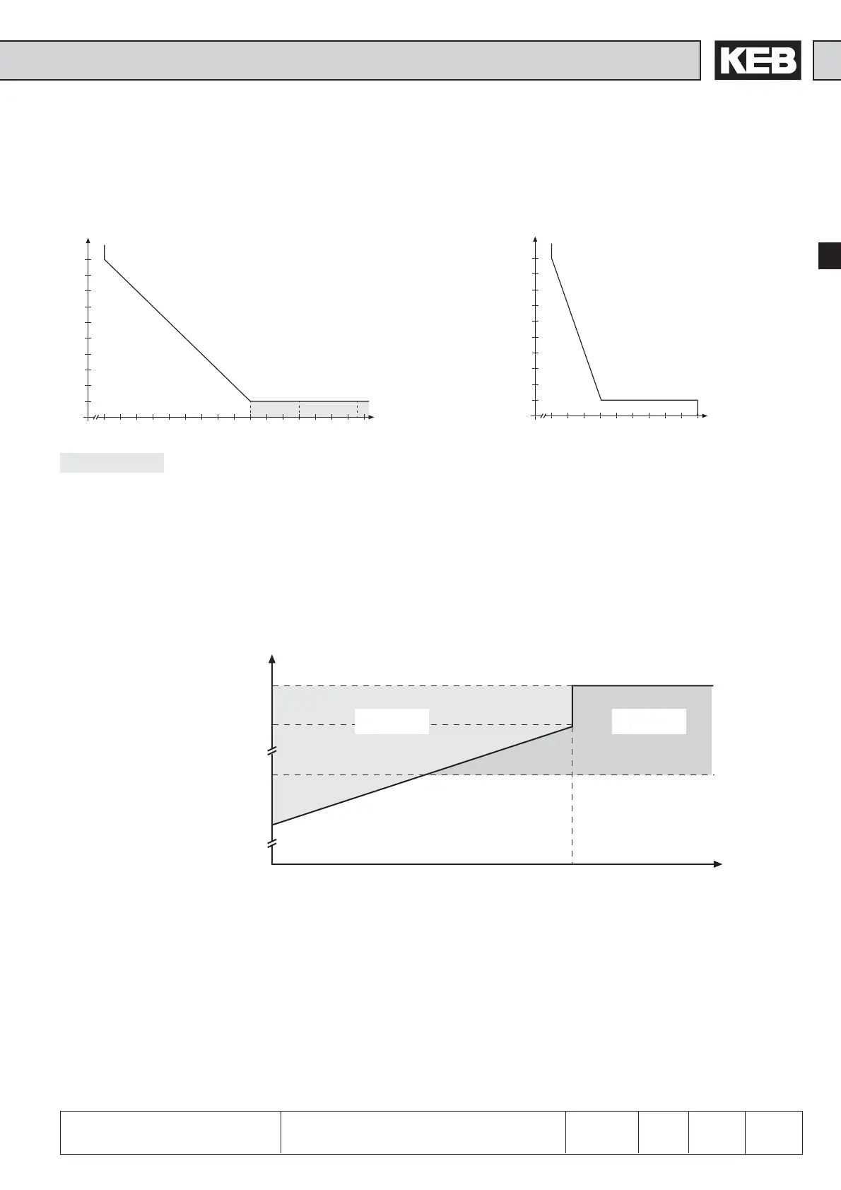
2.1.8 Overload curve
Time [s]
Load [%]
30
60
90
120
150
180
210
240
270
300
0 105 110 115 120 125 130 135 140 145 150 160 170 180 190 200
210 220
The characteristic declines device-dependently in this range (see technical data)
On exceeding a load of 105 % the counter starts. When falling below the counter counts backwards. If the counter
achieves the overload characteristic that corresponds to the inverter the error E.OL is triggered.
Curve 1
30
60
90
120
150
180
210
240
270
300
0 105 110 115 120 125 130 135 140 145 150
Time [s]
Load [%]
Curve 2
2.1.9 Overload protection in the lower speed range
(only valid for F5-M and F5-S, stall current see technical data)
Load [%]
E.OL2 E.OL
Stall current
Short-time limit current
Min. frequency at
continuous full load
OC-tripping current
If the permissible current is exceeded a PT1-element (τ=280ms) starts, after its sequence of operation the error E.OL2 is
triggered.
Start of overload
integrator at 105%
f [Hz]
 Loading...


