6 10
KEB COMBIVERT F5
6
Name: Basis
17.02.03
Chapter Section Page Date
© KEB Antriebstechnik, 2002
All rights reserved
Functional Description Encoder Interface
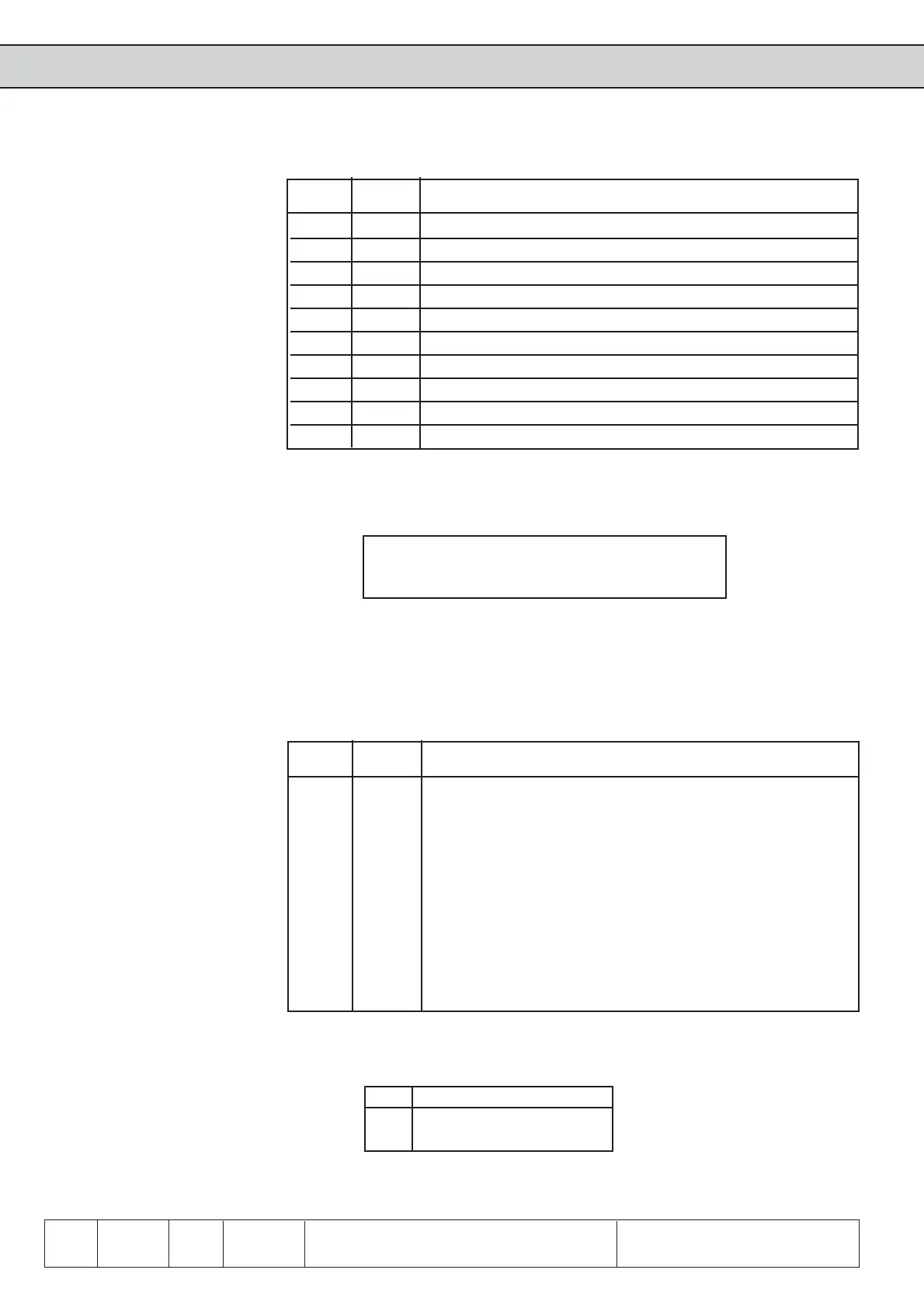
Incremental encoder output
Signal X3B Description
U
var
5 Supply voltage for encoder (see 6.10.2)
+5,2 V 4 Supply voltage for encoder (see 6.10.2)
0 V 9 Reference potential
A 1 Signal output A
_
A 6 Signal output A inverted
B 2 Signal output B
_
B 7 Signal output B inverted
N 3 Reference marking output N
_
N 8 Reference marking output N inverted
Shield Housing Shielding
The incremental encoder output gives out the signals recorded at the encoder interface
1:1 in RS422-specification over the second channel (e.g. master drive in synchronous
operation).
Operating mode
encoder 2 (ec.20)
With parameter ec.20 it is defined whether the encoder channel 2 shall work as input
or output. Precondition for that is a built-in switch-selectable encoder interface
(In.5†=†7).
ec.20 Function
0 Incremental encoder input
1 Incremental encoder output
Signal X3B Description
U
var
5 Supply voltage for encoder (see 6.10.2)
+5,2 V 4 Supply voltage for encoder (see 6.10.2)
0 V 9 Reference potential
A 1 Signal input A
_
A 6 Signal input A inverted
B 2 Signal input B
_
B 7 Signal input B inverted
N 3 Reference marking input N
_
N 8 Reference marking input N inverted
Shield Housing Shielding
The signal inputs of the second encoder interface support only rectangular signals.
Following specifications apply to the endocer interface 2 (X3B):
ï max. operating frequency of input f
G
= 300 kHz
ï internal terminating resistor R
t
= 150 Ω
ï 2Ö5 V high level at rectangular signals
 Loading...


