4.2 Diagnostic interfaces
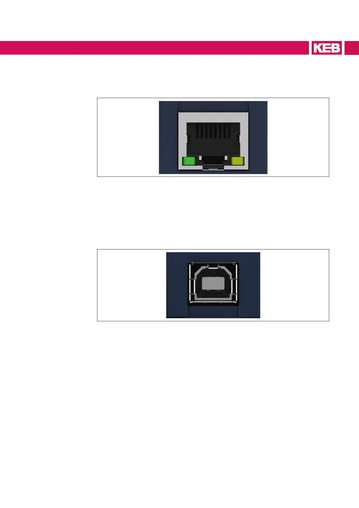
4.2.1 Ethernet interface
Figure 4: Ethernet interface
The ethernet interface emulates the diagnostic interface on the F6 device. DIN 66019 II
is used as protocol via TCP or UDP on port 8000 and KebFtp on port 8002. Additionally,
it can be accessed to parameters / objects of the operator. The operator responds to all
node addresses.
4.2.2 USB interface
Figure 5: USB interface
The DIN 66019 II protocol transmitted via USB is output by the operator on the serial
interface. The baud rate does not correspond to the baud rate set in COMBIVIS. The
operator and the control board check for the fastest possible baud rate. Additionally, it
can be accessed to parameters/objects of the operator. The USB interface is electrically
isolated. The operator responds to all node addresses.
17
INTERFACES

 Loading...


