6.6 Inverter parameters
Inverter parameter
Operator parameter
Parameter saving
Up/Download
Work list
File operations
FTP mode
Enter test mode
The menu item inverter parameter includes all available drive
controller parameters on the control board. They are func-
tion-related divided into groups. They are displayed on the
operator via the internal bus.
For the display of the drive controller parameters, the opera-
tor requires the appropriate conguration le, which must be
stored as *.blb le in the ash.
Alternatively, a similar type can be manually selected from
paras.blb.
The description of the drive controller parameters can
be taken from the programming manual F6.
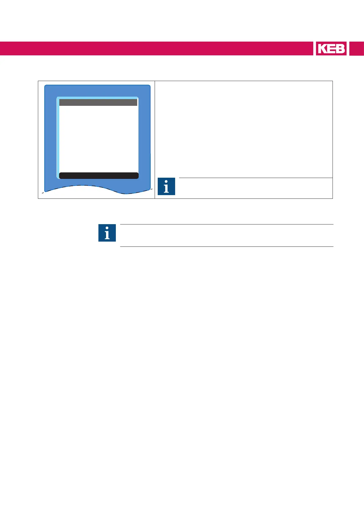
Figure 15: Inverter parameters
Inverter parameters are used when the result will be better, more economic or
trouble-free by following these procedures. Further information in the download
in the F6 Programming manual.
27
NAVIGATION

 Loading...


