2-8 Calibration Model 2750 Multimeter/Switch System Service Manual
3. When the unit is finished with short-circuit calibration, it will display the following
prompt:
OPEN CIRCUIT
4. Remove the calibration short, and press ENTER. During this phase, the CALI-
BRATING message will be displayed.
NOTE Be sure to minimize movement near front input terminals. Excessive movements
can cause capacitive coupling errors, which could affect calibration accuracy.
DC volts calibration
After the front panel short and open procedure, the unit will prompt you for the first DC
voltage: +10V. Do the following:
1. Connect the calibrator to the Model 2750 as shown in Figure 2-2. Wait three min-
utes to allow for thermal equilibrium before proceeding.
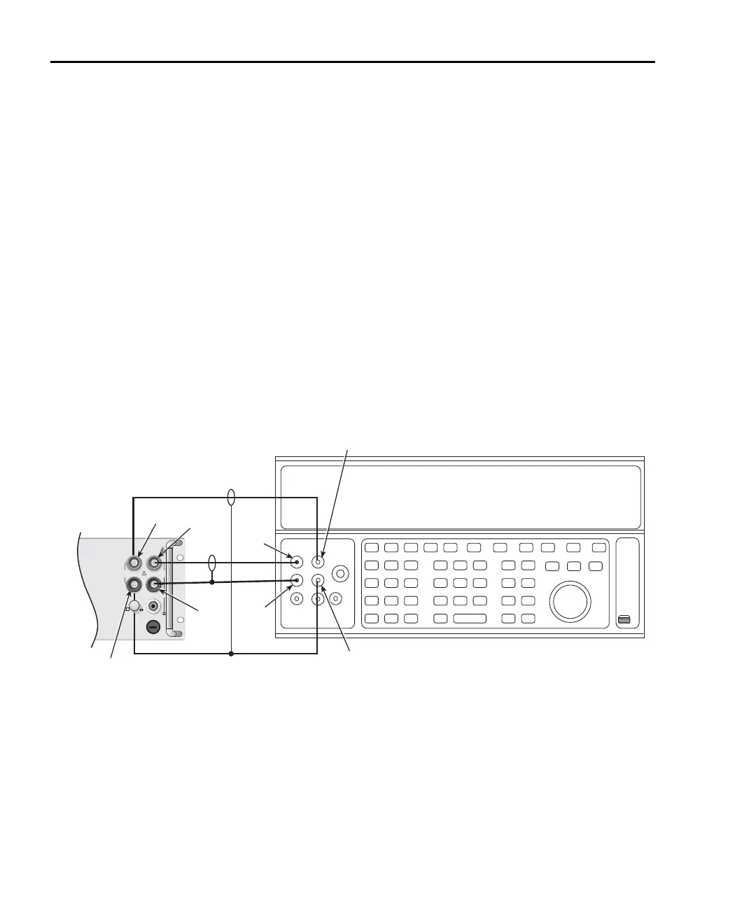
Figure 2-2
Connections for DC volts and ohms calibration
Input
HI
Input
LO
Output
LO
Output
HI
DC Voltage and Resistance Calibrator
Note: Use shielded, low-thermal cables to minimize noise.
Enable or disable calibrator external sense as indicated
in procedure.
Sense
LO
Sense
HI
Sense
LO
Sense
HI
!
F
500V
PEAK
FRONT/REAR
AMPS
HI
INPUT
LO
SENSE
Ω 4 WIRE
INPUT
350V
PEAK
1000V
PEAK
R
CAT I
3A, 250V
Model 2750
Front Panel